Gas dispersion plate and manufacturing method therefor

a technology of gas dispersion plate and manufacturing method, which is applied in the direction of coating, chemical vapor deposition coating, metallic material coating process, etc., can solve the problems of impractically expensive and time-consuming tooling execution, and achieve high corrosion resistance, improve the production yield of semiconductor devices, and improve the effect of corrosion resistan

Inactive Publication Date: 2007-04-12
COVALENT MATERIALS CORP
View PDF4 Cites 4 Cited by
  • Summary
  • Abstract
  • Description
  • Claims
  • Application Information

AI Technical Summary

Benefits of technology

[0036] The present invention enables to provide an inexpensive gas dispersion plate having a high corrosion resistance to halogen-based corrosive gasses and a plasma thereof, and capable of preventing particle generation from the gas hole, thereby contributing to an improvement in the production yield of the semiconductor devices.
[0037] The present invention also enables to provide a manufacturing method for a gas dispersion plate, having a high corrosion resistance to halogen-based corrosive gasses and a plasma thereof, and capable of preventing particle generation from the gas hole, thereby contributing to an improvement in the production yield of the semiconductor devices.

Problems solved by technology

It is also tried to remove the edge part by a chamfering, but it is impractically costly and time-consuming to execute a tooling on each of several hundred to several thousand holes present per a shower plate.

Method used


Image

  • Gas dispersion plate and manufacturing method therefor
  • Gas dispersion plate and manufacturing method therefor

Examples


examples

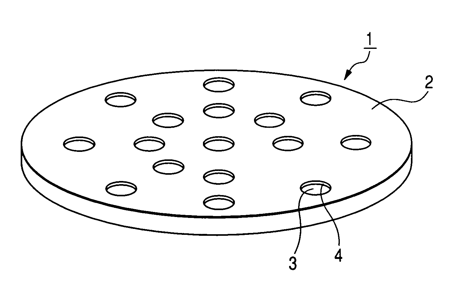
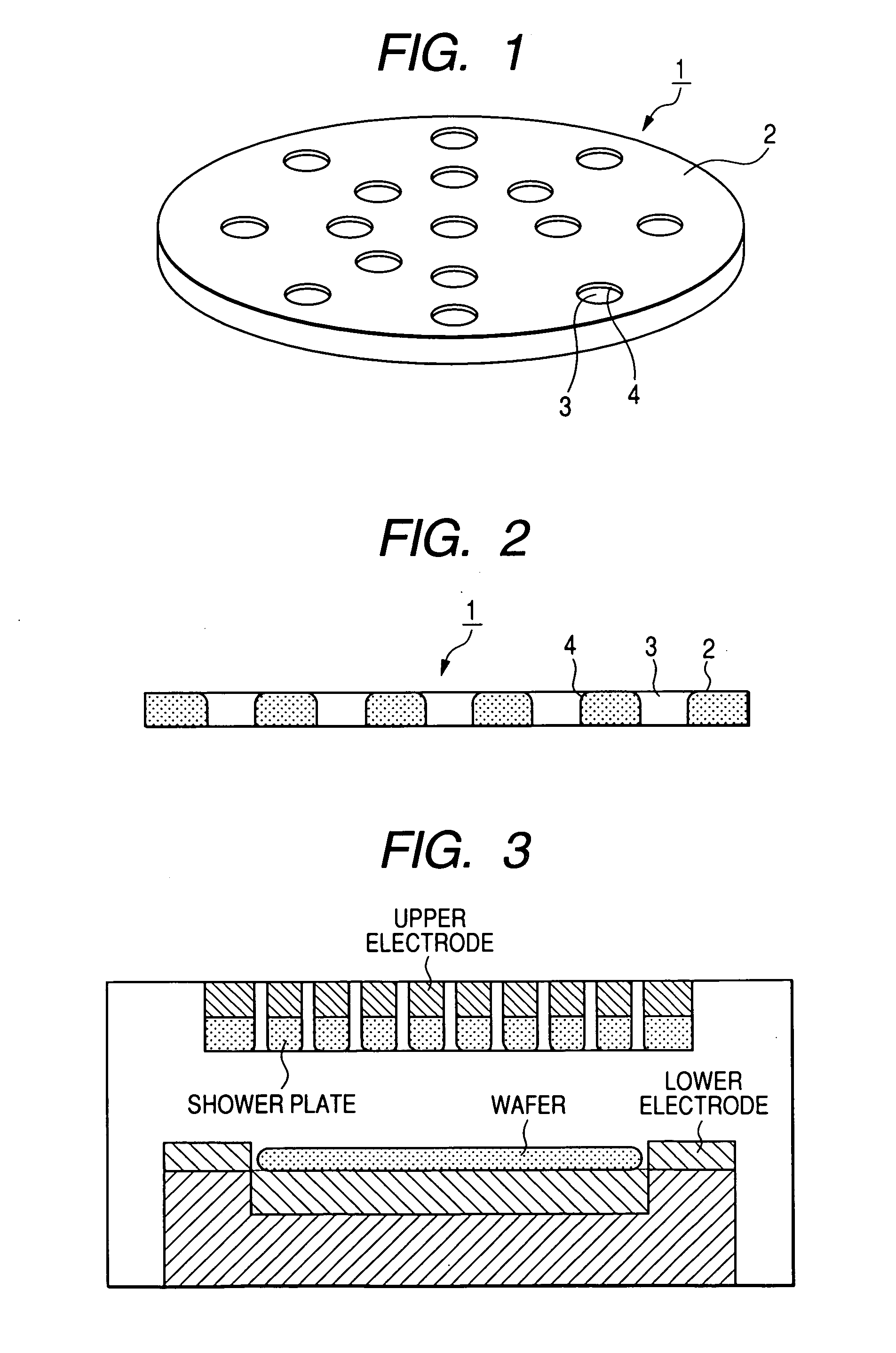
[0062] A shower plate was produced under the conditions shown in Table 2, was mounted in an etching apparatus as shown in FIG. 3, and subjected, in an etching of a semiconductor wafer, to an evaluation for particles, by counting particles deposited on the wafer, with a laser particle counter.

[0063] Obtained results are shown in Table 2.

TABLE 2rawmaterialsinteringpuritysinteringtemp.ultrasonicparticlesSample(%)atmosphere(° C.)vibration(count)Example 2-199.5hydrogen1800used8Comp. Ex. 2-198hydrogen1800used50Comp. Ex. 2-299.5hydrogen1750used25Comp. Ex. 2-399.5air1700used70Comp. Ex. 2-499.5hydrogen1800none45

[0064] As will be seen from Table 2, Example 2-1 meeting the conditions of the invention (Y2O3 with a raw material purity of 99% or higher, sintering at 1780-1820° C. in hydrogen atmosphere and ultrasonic vibration to working jig) showed a particle count as little as 8.

[0065] On the other hand, Comparative Example 2-1, having a raw material purity of 98% and not meeting the condit...


PUM

PropertyMeasurementUnit
temperatureaaaaaaaaaa
diameteraaaaaaaaaa
pressureaaaaaaaaaa

Abstract

To provide an inexpensive gas dispersion plate having a high corrosion resistance to halogen-based corrosive gasses and a plasma thereof, and capable of preventing particle generation from the gas hole, thereby contributing to an improvement in the production yield of the semiconductor devices. The gas dispersion plate includes one or plural gas holes in a base material formed by a Y2O3 ceramic material having a relative density of 96% or more, in which an edge part of the gas hole is formed by a sand blasting process into a rounded shape with a radius of curvature of 0.2 mm or more.

Description

TECHNICAL FIELD [0001] The present invention relates to a gas dispersion plate and a manufacturing method therefor, and more particularly to a gas dispersion plate in which an edge part of a gas hole is formed into a rounded shape by a sand blast process, to a gas dispersion plate in which a gas hole is formed under application of an ultrasonic vibration to a working jig, and a manufacturing method therefor. BACKGROUND ART [0002] In a semiconductor manufacturing apparatus such as an etching apparatus, a shower plate is provided directly above a wafer, for the purpose of uniformly dispersing a reactive gas. [0003] Such shower plate is commonly prepared with anodized aluminum, but, with an increasing density of plasma, various problems have become conspicuous, such as an aluminum contamination from the shower plate and particle (dust) generation by a peeling of the anodized film. [0004] In order to avoid such drawbacks, it has been tried to coat the surface of the shower plate with a ...

Claims


Application Information

Patent Timeline
Patent Type & Authority Applications(United States)
IPC IPC(8): H01L21/306C23F1/00C23C16/00
CPCC04B41/009C04B41/53C04B41/91C23C16/45565C04B35/505H01J37/3244
Inventor MURATA, YUKITAKANAGASAKA, SACHIYUKIMORITA, KEIJIWATANABE, KEISUKEWAKABAYASHI, SHIGENORI
Owner COVALENT MATERIALS CORP
Why Eureka
Try Eureka