

Anthrylarylene derivative, material for organic electroluminescence device and organic electroluminescence device using same
an anthrylarylene and derivative technology, applied in the field of anthrylarylene derivatives, can solve the problems of low glass transition temperature (tg) and inability to evaluate these compounds, and achieve the effects of good light emission efficiency, long life and sufficient glass transition temperatur
- Summary
- Abstract
- Description
- Claims
- Application Information
AI Technical Summary
Benefits of technology
Problems solved by technology
Method used
Image

Examples
synthesis example 1 (
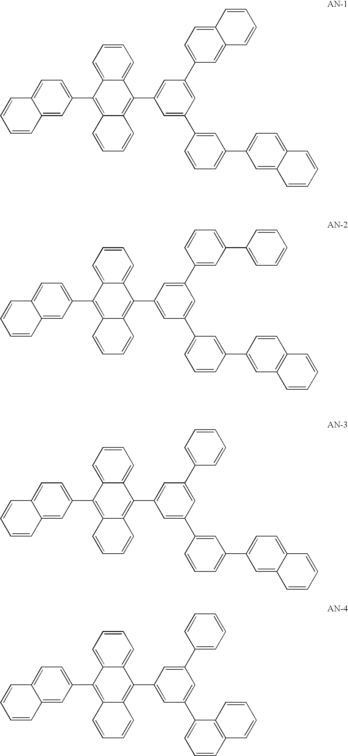
Synthesis of AN-4)
[0144] Under the atmosphere of argon, 20 g of 3,5-dibromobiphenyl synthesized from 3,5-dibromoiodobenzene and phenylboronic acid was dissolved into 200 ml of anhydrous THF, and the resultant solution was cooled at −70° C. To the cooled solution, 42 ml of a 1.6 M hexane solution of normal-butyllithium was added dropwise, and the resultant mixture was stirred for 30 minutes. Then, 19 g of 1,2-diiodoethane was added, and the obtained mixture was stirred for 5 hours. After the mixture was left standing for one night, water and methylene chloride were added. Then, sodium hydrogensulfite was added until dark brown color of the reaction mixture turned to yellow color. The organic layer was obtained by extraction, washed with water and a saturated aqueous solution of sodium chloride and dried with anhydrous sodium sulfate, and the solvent was removed using an evaporator. The obtained residue was purified in accordance with the silica gel column chromatography (the developi...
synthesis example 2 (
Synthesis of AN-10)
[0147] The same procedures as those conducted in Synthesis Example 1 were conducted except that 2-naphthaleneboronic acid was used in place of 1-naphthaleneboronic acid, and the object compound (AN-10) was obtained as a white solid substance (the yield: 55%). The obtained compound was examined in accordance with FD-MS (the field desorption mass analysis). Since it was found that m / z=582, which corresponded to C46H30=582, the obtained compound was identified to be AN-10.
synthesis example 3 (
synthesis of AN-14)
[0148] Commercial 2,6-dibromonaphthalene in an amount of 12 g, 11 g of commercial 3-biphenylboronic acid and 180 ml of toluene were mixed together. Then, 5.7 g of tetrakis(triphenylphosphine)palladium and 90 ml of a 2 M aqueous solution of sodium carbonate were added, and the reaction system was purged with argon. After the reaction mixture was heated under the refluxing condition for 7.5 hours, the reaction mixture was cooled by leaving standing. The formed crystals were separated by filtration and subjected to extraction with toluene. The obtained organic layer was washed with water and a saturated aqueous solution of sodium chloride and dried with anhydrous sodium sulfate, and the solvent was removed using an evaporator. The obtained residue was purified in accordance with the silica gel column chromatography (the developing solvent: hexane / toluene=5 / 1), and 7.8 g of 2-(biphenyl-3-yl)-6-bromonaphthalene was obtained as a white solid substance (the yield: 51%). ...
PUM
| Property | Measurement | Unit |
|---|---|---|
| Time | aaaaa | aaaaa |
| Time | aaaaa | aaaaa |
| Time | aaaaa | aaaaa |
Abstract
Description
Claims
Application Information