Pass-through restraint electrolytic implant delivery systems

a technology of electrolysis and implant, which is applied in the field of passing through restraint electrolysis implant delivery system, can solve the problems of clinical practicality, basic mechanical feasibility, and the significant issue of system actuation internal forces, and achieve the effects of reducing the risk of electrocoagulation

Inactive Publication Date: 2007-05-03
BIOSENSORS INT GROUP
View PDF107 Cites 16 Cited by
  • Summary
  • Abstract
  • Description
  • Claims
  • Application Information

AI Technical Summary

Benefits of technology

[0040] More particularly, a number of methods according to the present invention involve the manner in which the delivery system operates in releasing an implant. In one such method in which the implant is restrained at two sides, a first side is released by an electrolytic latch, followed by automatic release of the second side, wherein the automatic action is initiated by release of the first side. In another method, two independently releasable ends are released one after the other. This action is accomplished not by the contemporaneous erosion of an electrolytic member on each side of the implant (with staged release controlled by different amounts of material to erode as is known, and suitable for certain variations of the invention disclosed herein) but, rather, by selecting and eroding material incorporated in separate electrical circuits. Yet another delivery method is contemplated in which an electrolytic component is released only on one side of the implant. Such action may be followed by a mechanical release action such as withdrawing or tearing a sheath member manually or activating a “muscle wire” to do the same. Another approach may involve withdrawing or advancing the delivery guide to effect final implant release from a second, slidably releasable means holding the other end of the implant.
[0041] Another aspect of the invention provides methods involving power profiles for electrolytic element erosion and hardware / systems and software to control the methods. While electrocoagulation (e.g., by thrombus formation in blood by blood cell attraction to a positive charge) can be a positive factor in embolic coil delivery, it has been appreciated that such action can severely hamper or interfere delivery of other types of implants. Rather than isolating the member to be eroded, however, an aspect of the present invention involves use of power profiles to ameliorate or eliminate any problems with electrocoagulation. Specifically, an AC signal is employed. Not to be bound by the theory, but it is believed that the negative charge of the cycle repulses blood cells. However, to effect the desired erosion, a net positive charge is required. Thus, a positive DC offset is applied to the AC voltage. The positive offset and amplitude of the AC signal yields higher peak voltages to drive electrolytic corrosion. Irrespective of electrocoagulation, these higher peak energies may result in increased erosion and consequent implant deployment. Numerous potential power profiles according to this general principle are detailed below. Furthermore, experimental results are provided which illustrate the effectiveness of such an approach.
[0042] Another approach according to the present invention involves system insulation in order to focus erosion, or at least maximize current density at the point of erosion. Generally, it is known that “fast acting” detachable systems can be produced by insulating or electrically isolating everything but that portion of the system where electrolytic erosion is desired. The present invention improves upon this concept in certain variations by producing system components with high-strength titanium or titanium alloy. In addition, they can be anodized to form an oxide layer insulative to DC voltage. The components are typically pre-anodized. Yet, when using higher voltages, the systems are “self-healing” such that any scratches, etc. exposing material to unintended corrosion / erosion will skin-over and maintain their integrity. Such a system is highly advantageous as it eliminates the need for polymeric insulation; further, such a system need not rely on the use of noble (or high Mendelev number) metal material selection to protect components that can be costly or cumbersome to apply, or cause failures if disturbed.

Problems solved by technology

Internal forces can be a significant issue with respect to system actuation.
Upon closer examination, each of the referenced systems has serious limitations—either in terms of clinical practicality, basic mechanical feasibility or both.
1) risk of tissue damage or vulnerable plaque dislodgement by drawing released tethers or bands past / between an open / opening stent and a vessel wall;
2) inability to employ drug elution matrix upon a stent because of direct connection of an erodable solder joint to the stent;
3) unpredictability of joint or release segment corrosion;
5) bulkiness in system design.

Method used


Image

  • Pass-through restraint electrolytic implant delivery systems
  • Pass-through restraint electrolytic implant delivery systems
  • Pass-through restraint electrolytic implant delivery systems

Examples


example 1

[0212] The impact of AC voltage on actual erosion / corrosion rates during bench tests of tensioned 0.002″ stainless steel wire was conducted. Setups were provided in which an insulated wire was equally tensioned and exposed along a 0.020 inch long section. The wires were placed in 38° porcine blood and power was applied. When applying 2V DC, it took 3-4 minutes to break the wire. When applying 2V DC and 10Vpp AC, time to separation ranged from 20-30 seconds. The setups tested under DC-only conditions were observed to generate roughly 0.040 inch balls of electrocoagulation on the ends of the wire opposite the eroded section. In marked contrast, the AC / DC power driven setups showed no visible electrocoagulation.

example 2

[0213] The same test piece setup described in Example 1 was used with a lower DC voltage. With only 1V DC the wire would not break even after 15 minutes of applied power. When a 10Vpp AC signal was added to the 1V DC signal, the sample test section broke in roughly 1 minute.

example 3

[0214] Tests were conducted to determine the improvement offered over the power supply provided by Target Therapeutics for detatching GDC® coils. First a comparative model was developed. The electrolytic “joint” in a GDC system was determined to be about a 0.005 inch long, 0.003 inch diameter stainless steel wire. In 38° porcine blood, with the Target Therapeutics power supply set at a 1 mA currently delivery setting, voltage metered by the power supply initially showed at 3V, rose to 6.5V for the majority of the deployment time, and then rose to 8V. Over a deployment time measured at 40 seconds, the average voltage observed was about 6.5V. In addition, a ball of electrocoagulation having about a 1 / 32 inch diameter was observed.

[0215] A “test joint” model was developed to compare a number of samples in performance. It employed a roughly identically sized exposed wire extension as described above, but no occlusive coil attached thereto. In eroding the wire extension with the Target ...


PUM


Abstract

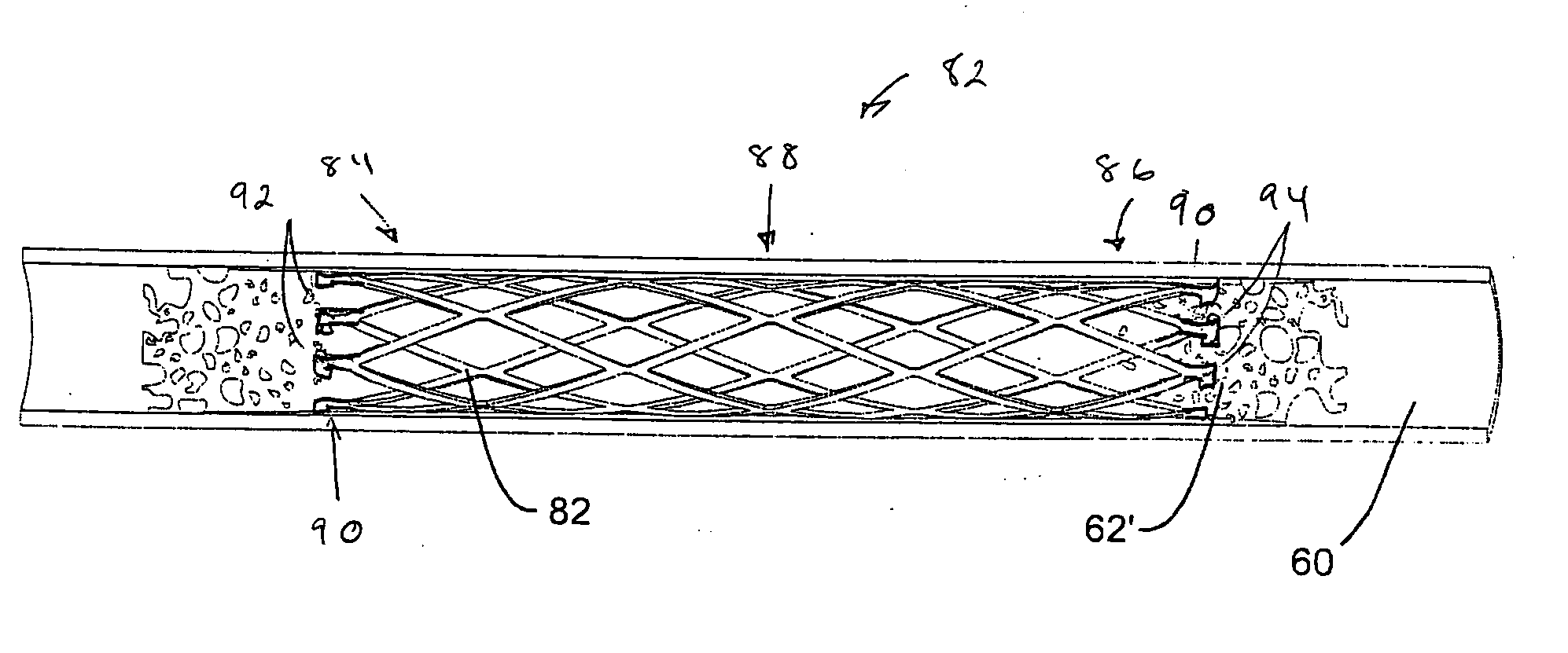
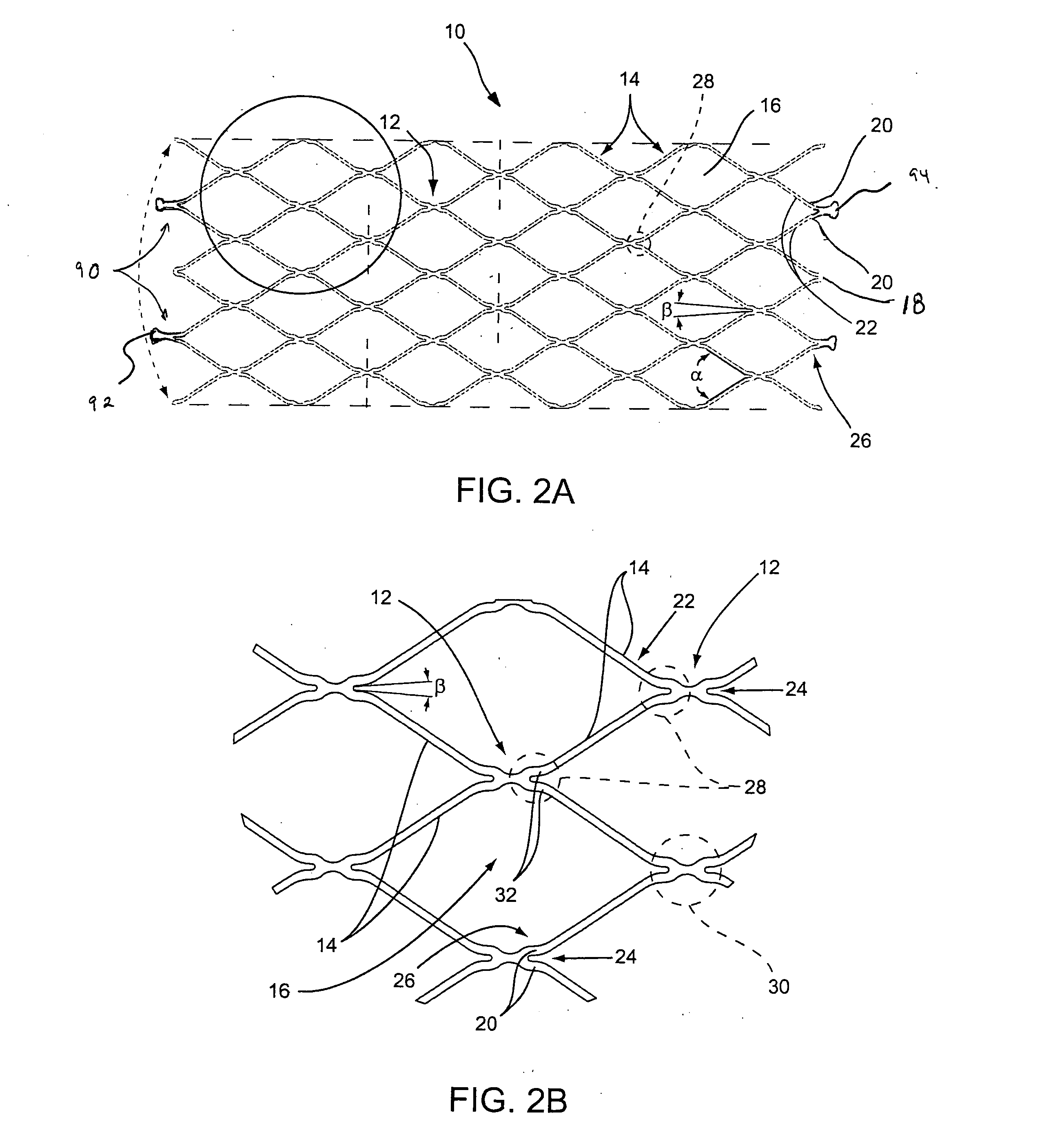
Medical devices and methods for delivery or implantation of prostheses within hollow body organs and vessels or other luminal anatomy are disclosed. The subject technologies may be used in the treatment of atherosclerosis in stenting procedures or be used in variety of other procedures. The systems may employ a self expanding stent restrained by one or more members released by an electrolytically erodable latch. Such release means do not connect directly to the implant, though one or more portions may contact it.

Description

BACKGROUND [0001] Implants such as stents and occlusive coils have been used in patients for a wide variety of reasons. One of the most common “stenting” procedures is carried out in connection with the treatment of atherosclerosis, a disease which results in a narrowing and stenosis of body lumens, such as the coronary arteries. At the site of the narrowing (i.e., the site of a lesion) a balloon is typically dilatated in an angioplasty procedure to open the vessel. A stent is set in apposition to the interior surface of the lumen in order to help maintain an open passageway. This result may be effected by means of a scaffolding support alone or by virtue of the presence of one or more drugs carried by the stent to aide in the prevention of restenosis. [0002] Various stent designs have been developed and used clinically, but self-expandable and balloon-expandable stent systems and their related deployment techniques are now predominant. Examples of self-expandable stents currently i...

Claims


Application Information

Patent Timeline
Patent Type & Authority Applications(United States)
IPC IPC(8): A61F2/06
CPCA61F2/88A61F2/95A61F2250/0071A61F2002/9511A61F2002/9522A61F2002/9505A61F2/9522
Inventor LICATA, DAVID
Owner BIOSENSORS INT GROUP
Why Eureka
Try Eureka