Laser-based maintenance apparatus

a maintenance apparatus and laser technology, applied in the direction of instruments, specific gravity measurement, greenhouse gas reduction, etc., can solve the problems of increased costs, noise and crack depth measurement, and no proposal for an overall system, so as to reduce the time of working processing and reduce the cost

Active Publication Date: 2007-07-12
KK TOSHIBA
View PDF6 Cites 65 Cited by
  • Summary
  • Abstract
  • Description
  • Claims
  • Application Information

AI Technical Summary

Benefits of technology

[0166] According to such laser maintenance apparatus of the characters mentioned above, it is not necessary to exchange the devices each time of test work or maintenance work, so that these works can be effectively and efficiently performed, resul...

Problems solved by technology

Exchanging the nondestructive testing device and the laser maintenance apparatus for each task extends the work time in the perspective of the overall task from testing to preventive maintenance, causing the problem of increased costs.
On the other hand, with regard to laser ultrasonic flaw detection devices, while proposals have been made regarding the feasible base technology of using the basic device configuration and flaw detection method, for flaw detection testing of the inner cylinder face of bottom-mounted instrumentation tubes, no proposal has been made regarding an overall system of a nondestructive testing device for bottom-mounted instrumentation tubes combined with preventing maintenance using laser.
In the case that the test object with a crack is an inner surface of a cylinder as described above, there are several problems such as noise and crack depth measurement.
However, if the positions for generation and detection or reception are only for irradiating from a distance in the same direction, as has been the case conventionally, the crack initiated in the axis direction of the test object cannot be sandwiched, and measuring the depth of the crack has been impossible.
Further, with the form of the irradiation head which contains the optical elements internally, depending on the form of the irradiation head, if the inner surface of the cylinder which is the test object has minute curved portions, the work of inserting into and removing from the cylinder which is the test object of the irradiation head becomes inefficient.
Further, in the case in which the test object is small, or in the case in which the test object is in a narrow portion, it is difficult to install the surface-wave probes.
Moreover, the conventional non-contact flaw-inspection method using laser light provides a problem wherein the data obtaining time for obtaining more detailed data and inspecting a flaw improving resolution becomes huge.
Accordingly, there poses a problem in which the capacity of a recording medium for recording obtained data and the flawed portion detection analysis time increase, and there also causes complex work for extracting necessary portions alone from the large quantity of data.
The application is expected in cases wherein the measurement subject is in a high temperature state, or is placed in a high location, or is placed in a high radiation area, or is very small and in a complicated shape so that contact with testing equipment is difficult, or in industrial technological fields wherein the ability to approach in close proximity is poor and a remote non-contact measurement method is required.
However, in a site environment such as a power plant or manufacturing line, when a conventional laser ultrasonic reception method and device as described above are used for a long time for defective flaw detecting or measurement work with ultrasonic waves, the following adverse effects are caused by position shifting of the optical elements due to temperature changes or oscillation in the device setting environment, and temperature changes of the coolant water used with the device, or time degradation of receiving laser excited by flash lamps used in a laser ultrasonic reception method and device:
(4) control unstable or control impossible of the resonator length of a Fabry-Perot interferometer.
In other words, there have been fatal problems such as the flaw detection operation becoming unstable and the flaw detection precision decreasing due to the adverse device states.
Moreover, in order to secure a fixed device state over a long period of time, the conditions needed to be adjusted frequently and the operation became complicated and flaw detecting costs increased greatly.
In addition, tamper-proofing of the test data or test reports is also necessary.
That is, in the above prior art technology, when the length of the flaw C becoming smaller than the width of a surface wave beam generating the flaw portion, the amount of attenuation of the surface wave receives is influenced by both the depth and length of the flaw, (in the surface wave beam, a part thereof is attenuated by generating the ...

Method used


Image

  • Laser-based maintenance apparatus
  • Laser-based maintenance apparatus
  • Laser-based maintenance apparatus

Examples


fifth embodiment

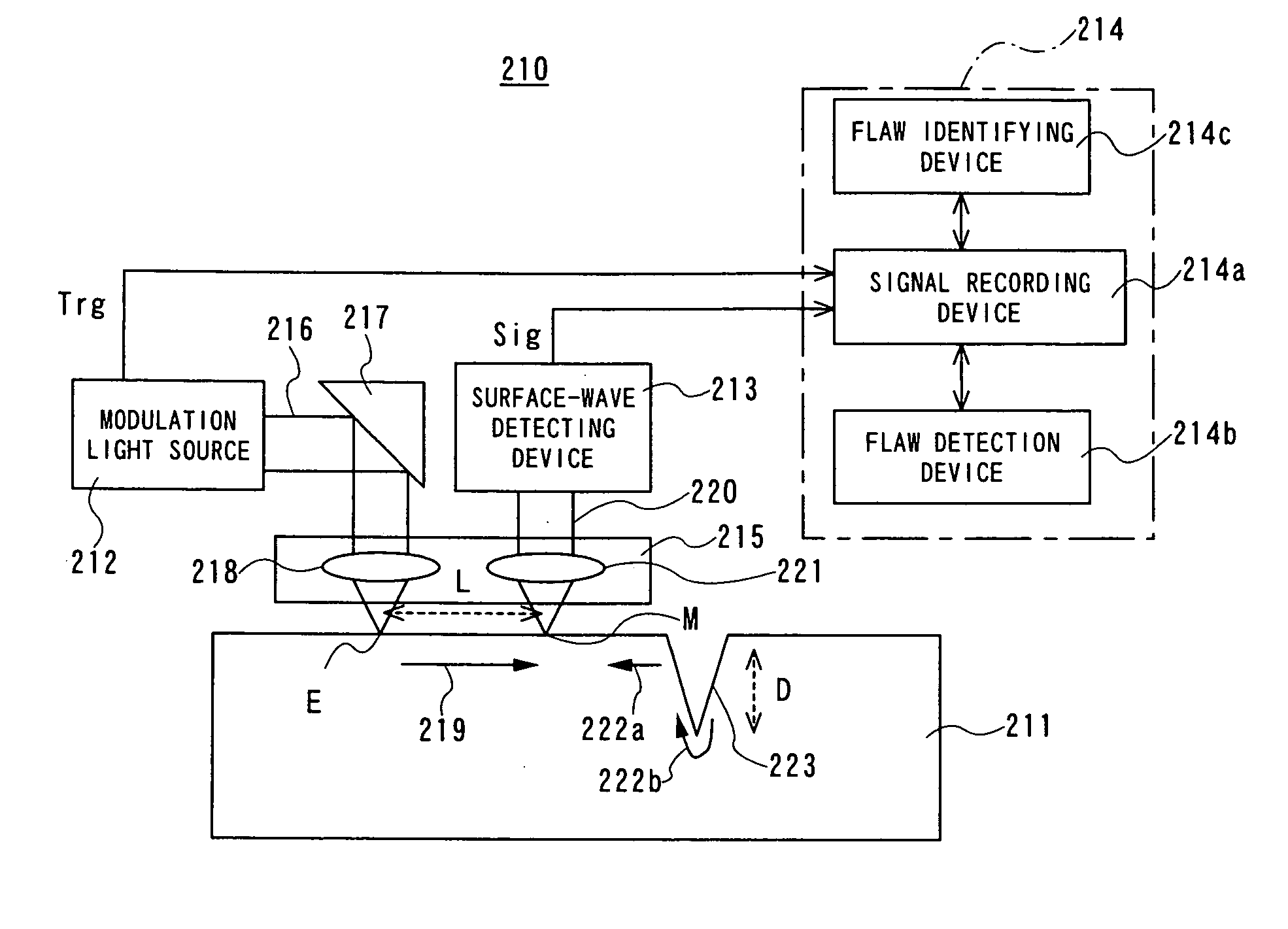
[0621]FIG. 38 is a block diagram illustrating the entire configuration of a fifth embodiment of a laser ultrasonic inspecting device 210C of the present invention. In this laser ultrasonic inspecting device 210C, a surveillance camera 229 is provided to the laser ultrasonic inspecting device 210A according to the second embodiment shown in FIG. 34.

[0622] The surveillance camera 229 is principally for imaging the test object 211, the scan surface to be scanned over the surface thereof and a surface inspecting working, recording the imaged signal to the signal recording device 214a, and displaying the recorded signal on a display screen. The image-captured (imaged) signal may be generated to the remote-monitoring device 228 shown in FIG. 37 via the signal recording device 214a so that the captured image is displayed on the display screen.

[0623] That is, generally, as for the procedures of the surface inspection of the test object 211, visual inspection prior to implementation and vi...

sixth embodiment

[0626]FIG. 39 is a schematic diagram illustrating the configuration according to a sixth embodiment of a laser ultrasonic inspecting system 230 of the present invention. In this laser ultrasonic inspecting system 230, either one of the above laser ultrasonic inspecting devices 210, 210A, 210B, and 210C is disposed in a container 231, and one or more air conditioners 232 serving as one example of a temperature controller are also disposed in this container 231.

[0627] According to this laser ultrasonic inspecting system 230, the temperature and humidity in the container 231 can be controlled in the temperature and humidity suitable for either one of the laser ultrasonic inspecting devices 210, 210A through 210C by the air conditioners 232 and 232, and therefore, particularly even in an environment of high heat and high humidity such as in the summertime, the laser ultrasonic inspecting devices 210, and 210A through 210C can be normally operated, thus ensuring the precision and qualit...

seventh embodiment

[0628]FIG. 40 is a schematic diagram illustrating the configuration of a seventh embodiment of a laser ultrasonic inspecting system 230A according to the present invention. In this laser ultrasonic inspecting system 230A, either one or more, two, for example, of the laser ultrasonic inspecting devices 210, 210A, 210B, and 210C are classified into an optical system 210L including an optical system such as a laser light-resource, and an electric system 210E including the other control systems other than the optical system, which are accommodated within containers 231L and 231E, respectively. The electric system containers 231E are stacked on the respective optical system containers 231L and erected in two layers on the floor F.

[0629] The optical system mentioned herein may include the modulation light source 212, a surface-wave detecting device 213, a scanner 215, an irradiation optical system 217, a lens system 218, and a shutter device 224. The electric system mentioned herein may ...


PUM


Abstract

A laser maintenance apparatus is provided with a laser system including a laser light source and an optical system and emitting a laser light, a light transmitting device for generating the laser light emitted from the laser system, and a laser irradiation device for irradiating the laser light generated by the light transmitting device to an object portion. The laser system includes an element for changing an irradiation condition of the laser light.

Description

BACKGROUND OF THE INVENTION [0001] 1. Field of the Invention [0002] The present invention relates to a technical field of flaw detection and preventive maintenance by using an ultrasonic, preferably, laser, maintenance apparatus, wherein both laser nondestructive testing and laser prevention maintenance can be carried out, and particularly relates to an ultrasonic, i.e., laser-based (or merely, laser), maintenance apparatus capable of carrying out flaw testing and prevention maintenance without interchanging devices. The present invention also relates to a surface testing or inspecting, or processing technology utilizing laser such as laser-ultrasonics, which are related to the laser maintenance technology mentioned above. [0003] 2. Related Art [0004] One way of ensuring continuous integrity of tubular structures in nuclear reactors is to nondestructively inspect (test) and measure whether there is no initiation of cracks in the structure or no material deterioration thereof and to ...

Claims


Application Information

Patent Timeline
IPC IPC(8): G01N29/00
CPCF22B37/003G01B11/161G01B17/02G01N29/043G01N29/0645G01N29/07G01B2290/25G01N2291/0258G01N2291/02854G01N2291/0421G01N2291/2636G21C17/003G21C17/017G01N29/2418Y02E30/30G21C17/00
Inventor OCHIAI, MAKOTOONO, YOSHIAKIMIURA, TAKAHIROSHIMAMURA, MITSUAKIYODA, MASAKIKURODA, HIDEHIKOCHIDA, ITARUOSAKATA, FUKASHIYAMAMOTO, SATOSHITSUCHIHASHI, KENTAROSAEKI, RYOICHIYOSHIDA, MASAHIROAIKAWA, TETSUROOKADA, SATOSHIONODERA, TORUTSUYUKI, AKIRA
Owner KK TOSHIBA
Why Eureka
Try Eureka