Hydrogen Generator Apparatus And Start-Up Processes

a hydrogen generator and hydrogen generating technology, applied in the direction of chemistry apparatus and processes, chemical/physical/physicochemical processes, and hydrogen separation using solid contact, etc., can solve the problems of increasing the severity of the challenge, the difficulty of storing and distributing hydrogen, and the difficulty of producing hydrogen in smaller scale units, so as to save gas compressor capital and operating costs, improve heat recovery efficiency, and save compression costs

Inactive Publication Date: 2007-08-23
HYRADIX INC
View PDF7 Cites 20 Cited by
  • Summary
  • Abstract
  • Description
  • Claims
  • Application Information

AI Technical Summary

Benefits of technology

[0022] The processes of this invention thus permit start-up without risk of catalyst damage due to condensing water on catalyst or coking due to introduction of hydrocarbon feed at elevated temperatures without sufficient steam. The specific heat capacity of steam is higher than, for example, air, so that more heat can be transferred to the hydrogen generator per unit amount of the heating gas. Further, steam can be generated by vaporizing liquid water in a compressed gas stream. The thus generated steam will not require gas compression thus enabling a saving on the gas compressor capital and operating costs required to provide a heating gas for start-up. Not only will an opportunity for savings in compression costs be realized, but also the partial oxidation reformer need not be subjected to as high a temperature at a given heating gas flow rate, to heat downstream unit operations to given temperatures.
[0023] In preferred embodiments of this invention where the gases to heat the hydrogen generator are heated by indirect heat exchange with a combustion effluent, the vaporization of liquid water in the heat exchanger can enable more efficient heat recovery from the combustion gases. One advantageous aspect of the invention is that a heat exchanger intended to heat a feed stream to a desired temperature for introduction into the reformer during normal operation may be useful as an indirect heat exchanger for the gases supplied to the reformer during start up.

Problems solved by technology

However, hydrogen is difficult to store and distribute and has low volumetric energy density compared to conventional hydrocarbon fuels such as gasoline.
Much greater challenges exist in producing hydrogen in smaller scale units than for the large industrial-scale hydrogen generators.
The severity of this challenge is increased where, due to fluctuating demand for hydrogen, the hydrogen generator may need to be shut down and restarted frequently.
One of the difficulties in providing a hydrogen generator that may face varying production demands involves enabling the hydrogen generator to be quickly started when a demand for hydrogen production exists.
For instance, stable operation of the hydrogen generator may not be achieved when the reformer is at or near steady-state conditions but the carbon monoxide reduction operations such as water gas shift or selective oxidation, are not at or near-steady state conditions.
Unfortunately, designs that favor desirable economics of operation may adversely affect the ability to achieve sought start up performance.
As the start-up procedure requires that the catalysts in the various reactors reach temperatures suitable for initiating the respective reactions, heat losses and added thermal mass imposed by the intervening equipment increase the difficulty of rapidly achieving the required catalyst operating temperatures.
Additionally, the materials of construction and potential for catalyst deactivation pose practical limits as to the type of start up procedure used.
An additional problem in starting up a hydrogen generator is that the generator contains a number of unit operations beyond the reforming operation and many of these operations will need to be raised to suitable temperatures for commencement of the intended function.
If start up occurs without the heat exchanger functioning as intended, e.g., due to a lack of water flow on the cold side, reformate might not be adequately cooled and damage to downstream operations and process instability or upsets, including a loss of hydrogen product quality, could occur.
However, with the heat absorbed in the reformer as well as heat losses to the environment, practical difficulties can exist in using this sequential approach for rapid heating of downstream units to temperatures desired to commence operation.
For instance, there is a practical limit on the temperature of the gas used to heat the reformer.
If the temperature is too high, risk of damage to catalysts and materials of construction exist.
Alternatively, lower temperature gas can be used, but the flow rate of the gas must be increased, which may involve added compression capacity and costs, to provide the same amount of heat.
While the start up process involving the steam purge is stated to reduce the formation of carbon, it is apparent that combustion within the reformer poses risks to the materials of construction and catalysts.
Maintaining a stable combustion can be difficult and an excursion could lead to undesirably high temperatures.
The variety of fuels capable of being used can be problematic as practical constraints favor those fuels having lower ignition temperatures such as methanol.
The addition of a flame burner adds complexity and cost to the reformer design.
A large amount of inert gas is required since subsequent catalyst layers are not heated until the first catalyst layer is heated.
Thus a long time period is required for the reformer to reach the required temperature.
This published patent application only relates to heating a reformer, and the problems noted would be exacerbated when downstream unit operations also need to be heated.
The application further notes that the amount of fuel that can be burned in the reformer is limited by the size of the combustor.

Method used


Image

  • Hydrogen Generator Apparatus And Start-Up Processes
  • Hydrogen Generator Apparatus And Start-Up Processes
  • Hydrogen Generator Apparatus And Start-Up Processes

Examples


Embodiment Construction

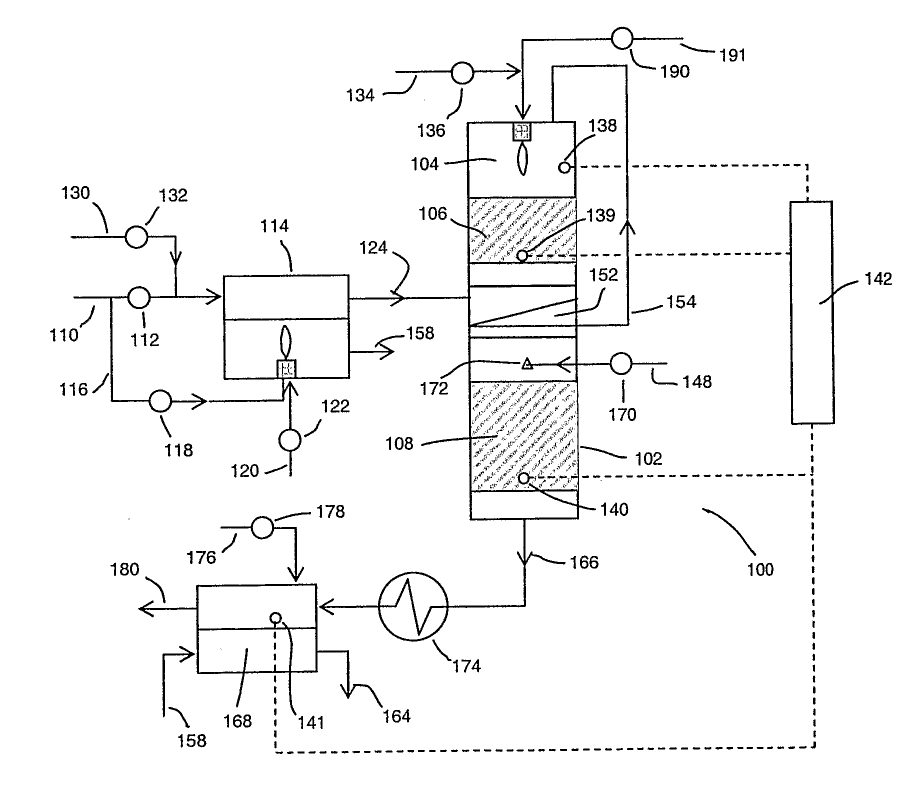
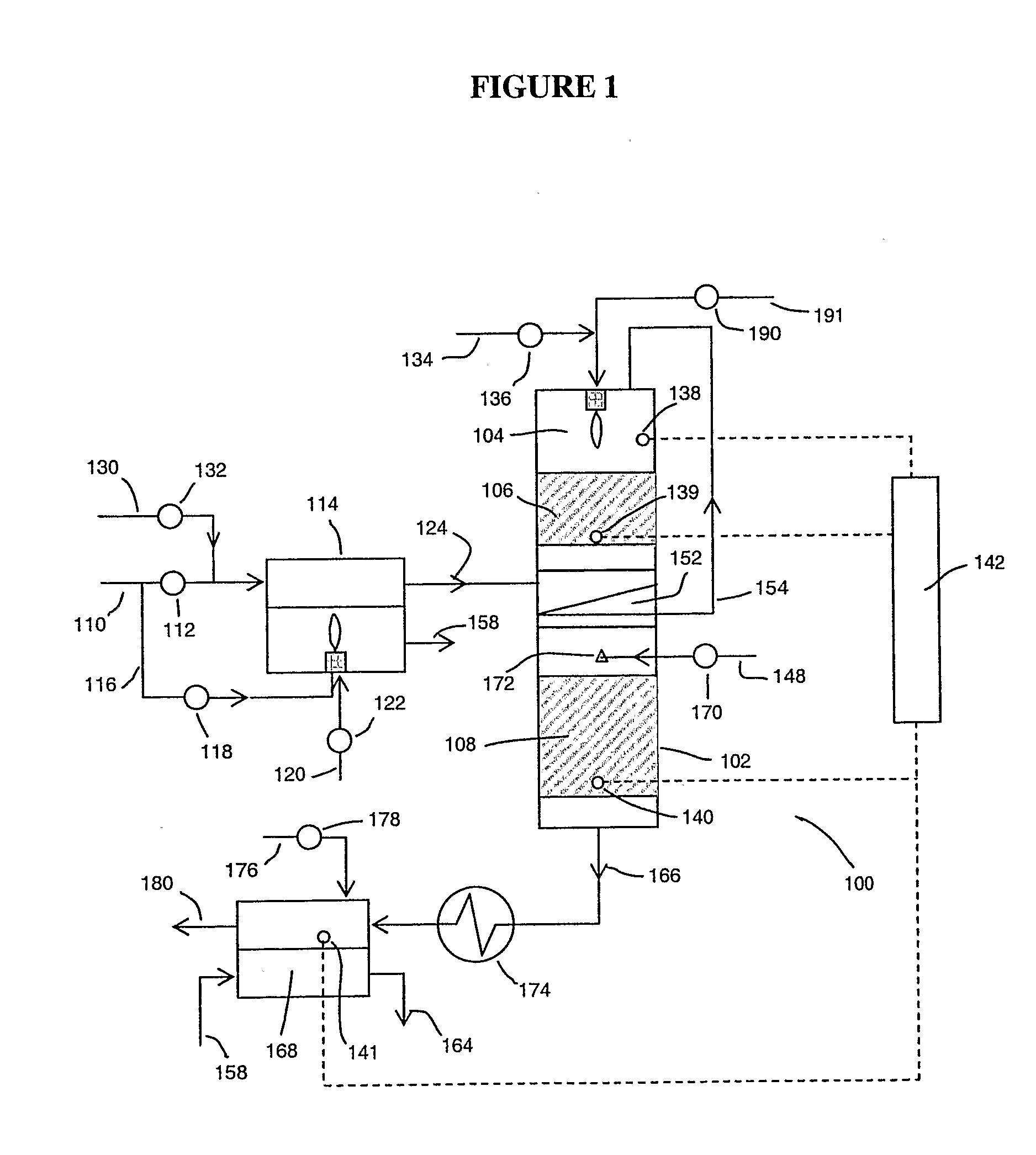
Overview of Hydrogen Generation Processes

[0038] The hydrocarbon-containing feeds used for reforming are typically gaseous under the conditions of reforming. Lower hydrocarbon gases such as methane, ethane, propane, butane and the like may be used. Because of availability, natural gas and liquid petroleum gas (LPG) are most often used as feeds. Biogas may also be used as a feed. Oxygenated fuels such as methanol and ethanol are included as hydrocarbon-containing feeds for all purposes herein.

[0039] Natural gas and LPG typically contain sulfur compounds, including odorants that are intentionally added for leak detection. Odorants conventionally used are one or more organosulfur compounds such as organosulfides, e.g., dimethyl sulfide, diethyl sulfide, and methyl ethyl sulfide; mercaptans, e.g., methyl mercaptan, ethyl mercaptan, and t-butyl mercaptan; thiophenes of which tetrahydrothiophene is the most common; and the like. The amount used can vary widely. For natural gas, the orga...


PUM

PropertyMeasurementUnit
temperatureaaaaaaaaaa

Abstract

Apparatus and process are provided to enable rapid start up of hydrogen generator (1) that use partial oxidation reforming. In the start up processes, a heated oxygen containing gas (110) is passed through the reformer (106) and at least one downstream unit operation (108) to achieve a first temperature regime. Then a heated steam containing gas is used to raise the temperatures of the reformer (106) and at least one downstream unit operation (108) to a second temperature regime at which partial oxidation reforming can be initiated.

Description

FIELD OF THE INVENTION [0001] This invention relates to apparatus for the generation of hydrogen and to processes for starting up hydrogen generating apparatus. BACKGROUND OF THE INVENTION [0002] Interest exists in using hydrogen as a fuel for motive and stationary power applications, e.g., as a fuel for fuel cells. A readily available source of hydrogen will be required for the use of hydrogen as a fuel to be broadly accepted. [0003] Processes for the generation of hydrogen are well known. Steam reforming of hydrocarbon-containing feedstock is a conventional source of hydrogen. Steam reforming of hydrocarbons is practiced in large-scale processes, often integrated with refinery or chemical operations. Thus, due to their large scale and available skilled labor force, sophisticated unit operations can be used while still economically producing hydrogen. [0004] Hydrogen must be readily available in order to be accepted as an alternative fuel. However, hydrogen is difficult to store an...

Claims


Application Information

Patent Timeline
Patent Type & Authority Applications(United States)
IPC IPC(8): C01B3/02B01J8/04B01J19/00C01B3/32C01B3/38C01B3/48
CPCB01J8/0221C01B2203/82B01J8/0492B01J8/0496B01J19/0026B01J2208/00061B01J2208/00203B01J2208/00362B01J2208/00504B01J2208/0053B01J2208/00646B01J2208/00716B01J2219/00006B01J2219/002B01J2219/00231B01J2219/00265C01B3/382C01B3/386C01B3/48C01B3/56C01B2203/0244C01B2203/0261C01B2203/0283C01B2203/043C01B2203/044C01B2203/047C01B2203/0844C01B2203/1241C01B2203/1288C01B2203/1294C01B2203/142C01B2203/1604C01B2203/1614C01B2203/1619B01J8/0453
Inventor CARPENTER, BRANDON S.HARNESS, JOHN R.RUSSELL, BRADLEY P.
Owner HYRADIX INC
Why Eureka
Try Eureka