Preformed particle gel for conformance control in an oil reservoir

a technology of conformance control and oil reservoir, which is applied in the direction of fluid removal, chemistry apparatus and processes, and well accessories, etc., can solve the problems of non-uniform displacement of oil within the reservoir, inability to homogenize the geologic properties of many reservoirs from which oil and gas are produced, and inability to achieve uniform water injection. achieve the effect of small initial siz

Inactive Publication Date: 2007-09-06
CHEMEOR
View PDF12 Cites 69 Cited by
  • Summary
  • Abstract
  • Description
  • Claims
  • Application Information

AI Technical Summary

Benefits of technology

[0018]These gel particles may be especially advantageous when used as selective plugging agents added to fresh or salt water injected into an oil reservoir. The features of having a controllable time delay before significant onset of swelling in water, and their smaller initial size give them the desirable capability to block target higher permeability rock layers further from the injection well than otherwise.

Problems solved by technology
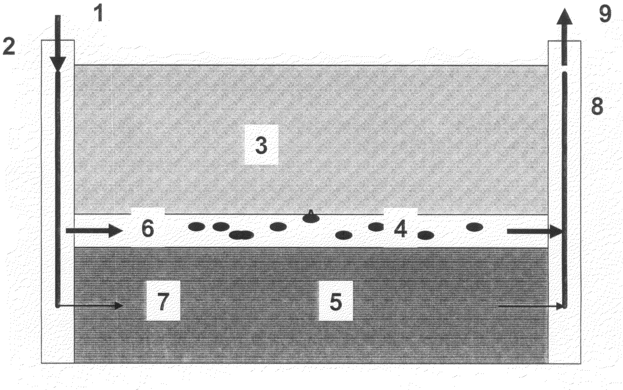
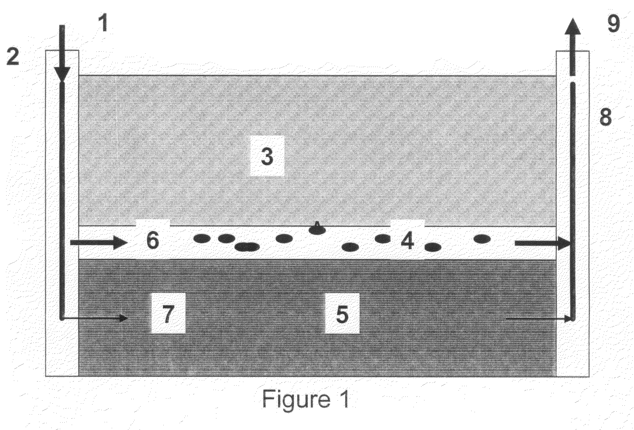
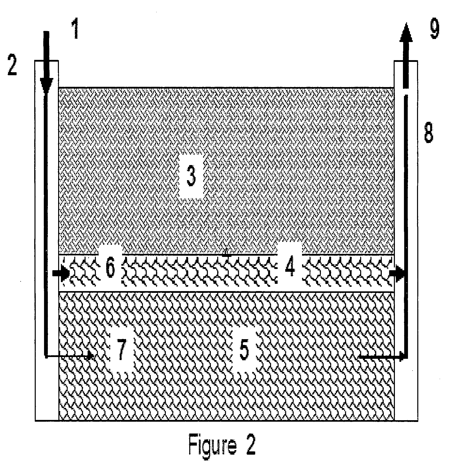
Many reservoirs from which oil and gas are produced are not homogeneous in their geologic properties (e.g. porosity and permeability).
A wide variation in the permeability (a property that measures the ability to transmit flow) among the geologic layer of rock that contain oil within its porous spaces in the subsurface reservoir causes such water injection to be not uniform, with the larger proportion of the water entering into the higher permeability geologic layers.
This condition results in a very non-uniform displacement of the oil within the reservoir, with most of the oil quickly mobilized from high permeability layers and little from the lower permeability layers.
The displacement process reaches the economic limit when the level of produced water is too high, and not enough oil is recovered, at a time when a large volume of oil remains in the bypassed, and not yet swept, lower permeability regions of the reservoir.
This is an undesirable result because any free oil in the high permeability formation is recovered quickly, but little of the oil from the lower permeability formation 5.
This behavior causes the process of water injection to become uneconomic soon, and there is still a high crude oil content left behind in the lower permeability formation 5.
However, these chemical conformance control methods have significant disadvantages: the bulk gel process described above requires high concentration of both polymer and cross-linker chemicals to make a strong gel, and the gelation time and physical properties are difficult to predict; sequential injection of polymer and crosslinker solution is questionable regarding controlling the time to create a gel in-situ and the strength of the gel that might form; colloidal dispersion gel (CDG) and the other previous methods described are unstable at more extreme reservoir conditions and therefore inadequate for reservoirs with high temperature (greater than 90 degree C.).
In addition, the CDG is not suitable when the salinity exceeds 5000 ppm Total Dissolved Solids (TDS) and it is not able to block effectively the very high permeability channels.
The PPG technology, however, has two important limitations.
This means that their desirable selective plugging action is confined to near the injection well, and thus these swollen particles are not able to penetrate deeply into the reservoir.
This limits the volume of the reservoir that can be treated to divert the injection water into the lower permeability areas that contain high oil content.
Secondly, the PPG particles commercially available have a relatively large size (hundreds of microns to millimeters in diameter).
This limits their application to plugging only very high permeability (tens of Darcies) layers.
However, it fails to realize the possible chromatographic separation in the subterranean formations when unreacted polymer and this cross linking agent are injected in separate solutions sequentially.
This separation of components can cause the inefficient cross-linking reaction and only a very weak gel in-situ.
Large percentages of surfactant are required for preparation of the microparticles via emulsification, which increases the product cost substantially.
In addition, there is an additional environmental issue by including the surfactant, not to mention the added complexity of working with an emulsion system to make the product.
The unexpanded particle size can only be as large as 10 micron due to the limitation of the microemulsion system.
Such small particle may get into the low permeability matrix target zones and inadvertently plug areas rich in residual oil.
Having a microemulsion will significantly increase the cost of the treatment product.
Moreover, the micron level particle size makes the product less desirable for treating very high permeability zones or fractured reservoirs.
Moreover, none of the references cited consider an expandable and hydrophilic polymeric particle made in a non-emulsion system that has controllable size, hardness, and swelling delay when added to fresh water or a salty brine.

Method used


Image

  • Preformed particle gel for conformance control in an oil reservoir
  • Preformed particle gel for conformance control in an oil reservoir
  • Preformed particle gel for conformance control in an oil reservoir

Examples


example 1

Preparation of Sample 27

[0035]In the present example, a single aqueous phase was prepared by adding 8.25 g acrylamide, 21.75 g sodium salt of 2-acrylamido-2-methylpropane sulfonic acid, 0.386 g polyethylene glycol 200 diacrylate, and 0.0004 g methylene bisacrylamide to 30.6 g deionized water with then mixing. At an ambient temperature of 15-30° C., an initiator mixture of 400 μl 5% sodium bromate and 400 μl 5% sodium bisulfite was added slowly to the solution with strong mixing. Within about 5 minutes, the reaction of polymerization took place with heat released, resulting in a fine gel.

example 2

Preparation of Sample 31

[0036]In this example, the procedure of example 1 was repeated except that 6.10 g polyethylene glycol 200 diacrylate and no methylene bisacrylamide were added to the formula. All other components and reaction conditions remained the same.

example 3

[0037]Comparison of swelling behavior of Sample 27 versus Sample 31 demonstrates the controllability the swell time and extent with our composition.

[0038]Sample 27 and Sample 31 suspensions were both prepared at a concentration of 1 wt % in distilled water and had the pH adjusted to be between 8 to 9. A portion of each suspension was aged at 40 degree C. and at 60 degree C. for 2 days. The results are shown below:

Temperature(Centigrade)Sample 27Sample 3140fluidfluid60stiff gelfluid

[0039]These results demonstrate that the composition of the Sample 27 is suitable for an application where the controlled monomer is designed to decompose within 2 days at 60 degree C. Furthermore, the fact that the Sample 27 remains in a fluid state over the same aging time at 40 degree C. indicate that for Sample 27 the mechanism for the loss of effectiveness of the controlled monomer, thereby causing particle expansion and a gel to form is related to its exposure to a greater extreme in temperature to 6...


PUM


Abstract

Expandable and hydrophilic polymeric particles may be made in a non-emulsion system, and with controllable hardness and delay in their time to swell in a fresh or salt water environment. These particles are prepared from combining monomers, controlled monomers, stable cross-linkers, initiators, and other agents, in aqueous solution. The controlled monomers induce kinetically controllable decomposition, degrading over time, thus inducing a desired time delay in particle swelling. The delay and degree of the swelling of the particles is controlled by selection of controlled monomer, stable cross-linking agents, monomers, and process conditions. These preformed particle gels are made to an initial particle size of 0.1 micron in diameter or larger via different grinding techniques. This composition is used for modifying the permeability of subterranean formations and thereby increasing the recovery rate of hydrocarbon fluids present in the formation.

Description

RELATED APPLICATION[0001]This application claims the benefit of U.S. Provisional Application No. 60 / 780,950, filed on Feb. 28, 2006, which is hereby incorporated by reference in its entirety as fully set herein.FIELD OF THE INVENTION[0002]The present invention relates to the field of hydrocarbon production. Particularly, the present invention relates to the manufacture of particles with improved physical and chemical characteristics that when added to injection water will further improve the crude hydrocarbon recovery from subterranean heterogeneous reservoirs.BACKGROUND OF THE INVENTION[0003]Many reservoirs from which oil and gas are produced are not homogeneous in their geologic properties (e.g. porosity and permeability). In fact, for many of such reservoirs, the differences in the permeability (ability to allow fluid flow) among the different geologic layers can vary as much as several orders of magnitude.[0004]Commonly a fluid, particularly water, is injected into an injection ...

Claims


Application Information

Patent Timeline
Patent Type & Authority Applications(United States)
IPC IPC(8): E21B43/22E21B33/138E21B33/128
CPCC09K8/508C09K8/516C09K8/512
Inventor TANG, HONGXIN
Owner CHEMEOR
Why Eureka
Try Eureka