Membrane electrode assembly and its manufacturing method

Inactive Publication Date: 2007-11-22
SHANGHAI HORIZON FUEL CELL TECH
View PDF8 Cites 34 Cited by
  • Summary
  • Abstract
  • Description
  • Claims
  • Application Information

AI Technical Summary

Benefits of technology

[0013] The MEA described herein can achieve superior water management at the catalyst layer level, can use an ultra thin electrolyte layer while maintaining high mechanical strength and can be fabricated with integrated peripheral areas in a simple and cost effective process. In one embodiment of this invention, this is accomplished by a thin catalyst film layer which contains a porous polymer membrane containing a mix of catalyst particles and ion-conductive polymers inside and on the surface of the porous polymer membrane.
[0014] One novel aspect is the use of a catalyst film layer which has a hydrophobic porous membrane containing catalyst particles and ionomers. An expanded polytetrafluoroethylene (PTFE) membrane is preferred as the hydrophobic porous membrane. Conventional hydrophobic catalyst layers are prepared by coating a catalyst slurry containing a carbon supported platinum catalyst, ionomer resins and PTFE resins at a ratio of 1:0.15:0.15 onto a solid electrolyte membrane or onto a gas diffusion layer in one step or in multiple steps. By employing the expanded PTFE membrane in the catalyst layer instead of the use of PTFE resins in conventional methods, unique advantages can be achieved.
[0015] A first advantage is that layers of different hydrophobic and hydrophilic properties can be created inside the catalyst film layer, and the hydrophobic and hydrophilic properties can be easily adjusted by modifying the thickness and porosity of the expanded PTFE membrane. By coating a catalyst slurry containing a mix of catalyst particles

Problems solved by technology

The MEA is the heart of a PEM fuel cell and there are significant challenges in MEA design and manufacturing.
One challenge is water management of the catalyst layer.
Neither of them addresses the water management problem well over a wide temperature range, and none of the catalyst layers can provide sufficient self humidification for the membrane in a wide temperature range.
Another challenge is to improve the proton conductivity of the solid pol

Method used


Image

  • Membrane electrode assembly and its manufacturing method
  • Membrane electrode assembly and its manufacturing method
  • Membrane electrode assembly and its manufacturing method

Examples


Embodiment Construction

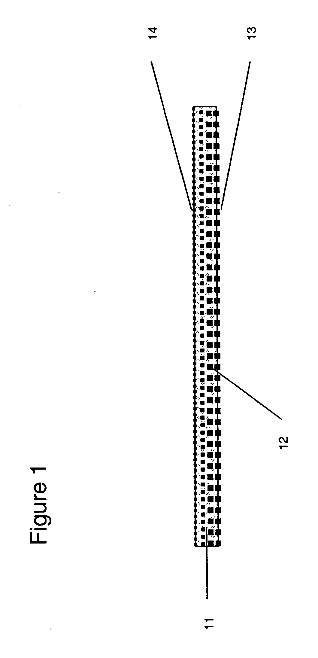
[0028] As shown in FIG. 1, a catalyst film layer is provided which includes a porous hydrophobic polymer membrane 11 and a mix 12 of catalyst and ionomer. Suitable porous hydrophobic polymer membranes include porous membranes of fluoropolymers, polypropylene, polyvinylidene fluoride. Preferred membranes include membranes of porous polytetrafluoroethylene, more preferably a membrane of expanded porous PTFE (sometimes referred to as ePTFE) produced by the process taught in U.S. Pat. No. 3,953,566 (to Gore). Porous hydrophobic polymer membrane 11 is preferred to have a thickness from 1 micron to 20 micron, porosity from 20%-95% and average pore size from 0.01 micro to 1 micron. The catalyst preferably comprises a very fine powder of a catalytic metal such as platinum. Furthermore, the catalyst is preferably mixed with a supporting material comprising a high surface area carbon, resulting in a platinum-on-carbon catalyst mixture. Such catalyst is available from commercial catalyst suppl...


PUM

PropertyMeasurementUnit
Thicknessaaaaaaaaaa
Thicknessaaaaaaaaaa
Thicknessaaaaaaaaaa

Abstract

A membrane electrode assembly including comprising of a central electrolyte layer a catalyst film layer adjacent to each side of the electrolyte layer, wherein the catalyst film layer includes a hydrophobic porous polymer membrane containing a mix of catalyst particles and ionomers inside the porous polymer membrane and on the surface of the porous polymer membrane.

Description

[0001] This application claims the benefit of U.S. Provisional Application No. 60 / 749,939, filed Dec. 13, 2005, incorporated herein by reference.TECHNICAL FIELD [0002] This invention relates to membrane electrode assemblies such as are used in fuel cells. BACKGROUND OF THE INVENTION [0003] Proton exchange membrane (PEM) fuel cells are electrochemical devices that convert the chemical energy of hydrogen into electrical energy without combustion. They have high potential to offer an environmentally friendly, high-energy density, efficient, and renewable power source for various applications from portable devices to vehicles and stationary power plants. [0004] The Membrane Electrode Assembly (MEA) is the heart of a PEM fuel cell and an MEA typically is comprised of a membrane, two or more catalyst layers and gas diffusion layers. A three layer MEA usually has catalyst coated to both sides of a central membrane and a five layer MEA will also include one gas diffusion layer on each side ...

Claims


Application Information

Patent Timeline
IPC IPC(8): H01M8/10
CPCH01M4/8642H01M4/881H01M4/8828H01M8/0291Y10T29/53204H01M8/1058H01M2300/0094Y02E60/521H01M8/1004H01M8/0289Y02E60/50Y02P70/50
Inventor GU, ZHIJUN
Owner SHANGHAI HORIZON FUEL CELL TECH
Why Eureka
Try Eureka