Scanner/optical system for three-dimensional lidar imaging and polarimetry

a lidar imaging and optical system technology, applied in the field of scanning lidar systems, can solve the problems of inability to achieve the capability through a simple scaling of the laser fire rate or power, inability to effectively use the available laser photons, and severe limitations in instrument mass and prime power usage, so as to reduce the size, power requirements, mechanical complexity, and the effect of high repetition ra

Active Publication Date: 2007-12-06
INTERGRAPH
View PDF17 Cites 83 Cited by
  • Summary
  • Abstract
  • Description
  • Claims
  • Application Information

AI Technical Summary

Benefits of technology

[0012]Apparatus embodying the present invention includes a microchip laser associated with a small diameter telescope. The microchip laser emits pulses of coherent light at a high repetition rate. The emitted laser pulses are collimated by the telescope and transmitted to the ground. Photons are reflected off the ground. The return photons are filtered through a spectral filter and through a spatial filter to reduce solar background noise. The telescope then receives the return photons and supplies them to a multi-pixel detector array or a multi-anode photomultiplier single photon detection system.
[0013]The use of relatively simple software algorithms based on post-detection Poisson filtering techniques enables the identification and extraction of surface sampling data from the more abundant optical background noise prior to on-board storage or transmission of data to the ground station.
[0014]An order of magnitude reduction in required telescope diameter greatly reduces the size, power requirements, and mechanical complexity of an external optical scanning system and allows the use of relatively inexpensive, modest diameter optical wedges or holographic optical elements to simultaneously scan both the transit and receive beams for-cross-track interrogation of the terrain while maintaining narrow fields of view for background noise suppression.
[0015]Performance is further enhanced by using state of the art photon counting array detectors or segmented anode photomultipliers, which are capable of providing sub-centimeter level ranging resolution as well as angularly resolving the source of a single photon event within the receiver field-of-view. With high angular resolution of the single photon source, the measured range becomes nearly a point-to-point measurement, i.e. from an internal altimeter reference point to a small area of uncertainty on the surface. The horizontal spatial resolution is determined by the angular resolving power of an individual pixel in the photodetector and the height of the host aircraft or spacecraft relative to the ground, and the surface area subtended by the pixel can be very small (1% or less depending on the number of detector elements) compared to the total laser beam area on the ground. The ranging precision then is limited by the laser pulse width, the timing capabilities of the range receiver, and the much-reduced residual spreading caused by the roughness of the surface and slope within the relatively small area viewed by a...

Problems solved by technology

As a result of this conventional design philosophy, spacecraft prime power and weight constraints typically restrict operations to modest repetition rates on the order of a few tens of Hz which, for a typical earth orbit ground velocity of seven kilometers per second, limits along-track spatial sampling to one sample every few hundred meters.
There is great motivation in obtaining higher along-track resolution and/or better cross-track coverage, but achieving this capability through a simple scaling of the laser fire rate or power is not practical from spacecraft.
This is especially true of altimeters for use in orbit about other planets where instrument mass and prime power usage is severely restricted.
In summary, the conventional high signal-to-noise ratio approach to laser altimetry does not make efficient use of the available laser photons.
First generation altimetric approaches are not well suited to generating the few meter level horizontal resolution and decimeter precision vertical (range) resolution on the global scale desired by many in the Earth and planetary science communities.
On Earth, the presence of manmade buildings and volumetric scatterers (such as tree canopies or other vegetation) generally makes waveform interpretation more complex and difficult.
One major challenge to the conventional approach is the sheer number of measurements required over a nominal mission lifetime of two to three years.
If one were to simply scale conventional approaches, one would clearly face severe pri...

Method used


Image

  • Scanner/optical system for three-dimensional lidar imaging and polarimetry
  • Scanner/optical system for three-dimensional lidar imaging and polarimetry
  • Scanner/optical system for three-dimensional lidar imaging and polarimetry

Examples


Embodiment Construction

[0029]The invention summarized above may be better understood by referring to the following description, which should be read in conjunction with the accompanying drawings. This description of an embodiment, set out below to enable one to build and use an implementation of the invention, is not intended to limit the invention, but to serve as a particular example thereof. Those skilled in the art should appreciate that they may readily use the conception and specific embodiments disclosed as a basis for modifying or designing other methods and systems for carrying out the same purposes of the present invention. Those skilled in the art should also realize that such equivalent assemblies do not depart from the spirit and scope of the invention in its broadest form.

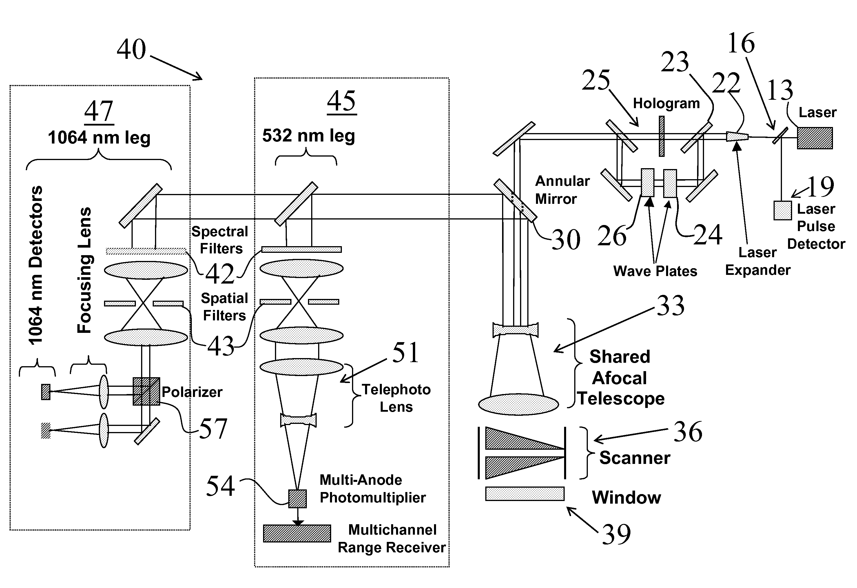
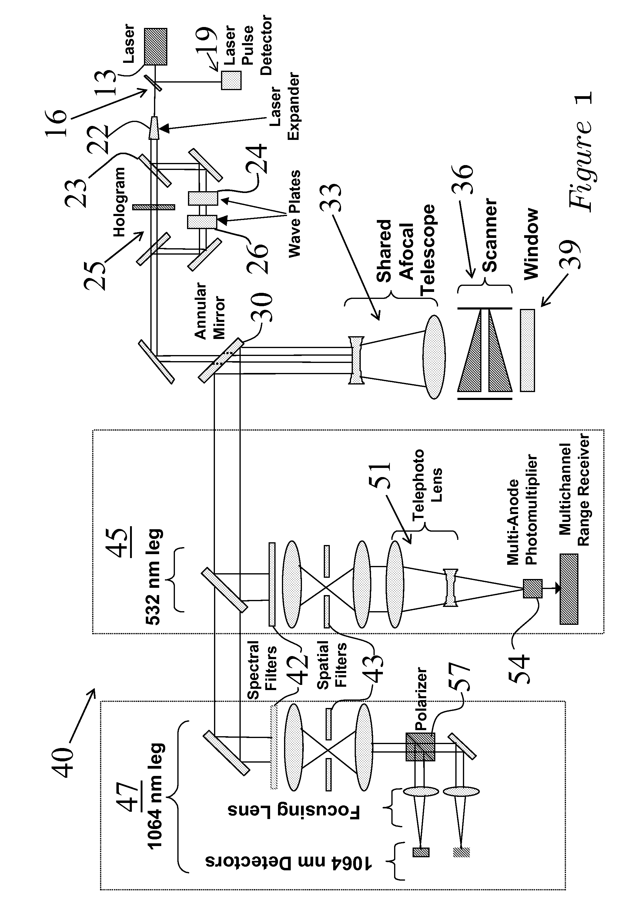
[0030]Referring to FIG. 1, an optical schematic for a combined three-dimensional LIDAR imager / laser polarimeter according to the present invention is shown generally as 10 in FIG. 1. A small fraction of the outgoing laser p...


PUM


Abstract

An optical scanner system for contiguous three-dimensional topographic or volumetric imaging of a surface from an aircraft or spacecraft is disclosed. A servo controller synchronizes the rotation rates of a pair of wedge scanners with high precision to the multi-kilohertz laser fire rate producing an infinite variety of well-controlled scan patterns. This causes the beam pattern to be laid down in precisely the same way on each scan cycle, eliminating the need to record the orientations of the wedges accurately on every laser fire, thereby reducing ancillary data storage or transmission requirements by two to three orders of magnitude and greatly simplifying data preprocessing and analysis. The described system also uses a holographic element to split the laser beam into an array that is then scanned in an arbitrary pattern. This provides more uniform signal strength to the various imaging detector channels and reduces the level of optical crosstalk between channels, resulting in a higher fidelity three-dimensional image.

Description

CROSS REFERENCE TO RELATED APPLICATIONS[0001]This application is based upon and claims benefits of copendng and co-owned U.S. Provisional Patent Application Ser. No. 60 / 809,626 entitled “SCANNER / OPTICAL SYSTEM FOR THREE-DIMENSIONAL LIDAR IMAGING AND POLARIMETRY,” filed with the U.S. Patent and Trademark Office on May 31, 2006 by the inventors herein. Copendng and co-owned U.S. Provisional Patent Application Ser. No. 60 / 809,626 is incorporated herein bay reference.STATEMENT REGARDING FEDERALLY SPONSORED RESEARCH AND DEVELOPMENT[0002]This invention was made and reduced to practice using US government funding under the U.S. Airforce Contract No. FA8650-05-C-1817 entitled “A 3D IMAGING AND POLARIMETIC LIDAR APPLICABLE TO MINI / MICRO UAV'S PROGRAM”. The US government has certain rights in this invention.FIELD OF THE INVENTION[0003]The invention relates generally to scanning LIDAR systems and in particular to a system for contiguous three-dimensional imaging and polarimetry of a topographi...

Claims


Application Information

Patent Timeline
IPC IPC(8): G01C3/08
CPCG01S17/89G01S7/499
Inventor DEGNAN, JOHN JAMESWELLS, DAVID NELSON
Owner INTERGRAPH
Why Eureka
Try Eureka