Cryogenically Cooled Solid State Lasers

a laser and cryogen technology, applied in lasers, laser cooling arrangements, laser details, etc., can solve the problems of thermal distortion, thermal gradient formation, and changes in the index of refraction of laser materials, so as to achieve high efficiency

Inactive Publication Date: 2007-12-27
SNAKE CREEK LASERS
View PDF53 Cites 43 Cited by
  • Summary
  • Abstract
  • Description
  • Claims
  • Application Information

AI Technical Summary

Benefits of technology

[0019] It is accordingly an object of the present invention to provide techniques and constructions for cryogenically cooling solid state lasers which are highly efficient, straight forward to implement and are compatible with different types of laser geometries and amplifier system architectures.
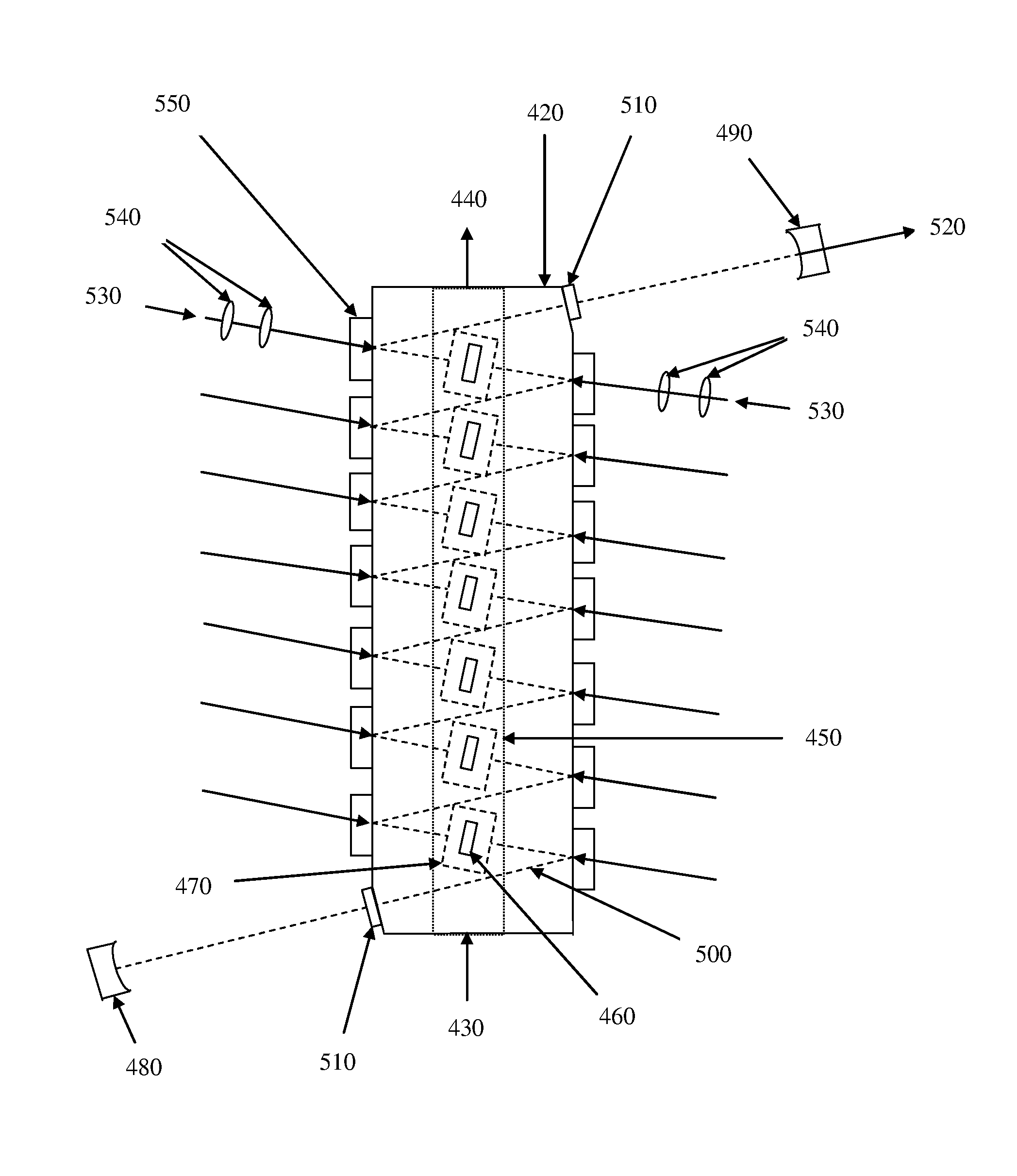
[0020] Unlike prior art in which optical pumping of the laser medium was accomplished by passing the pump light through an optically clear layer of cryogenic fluid, typically LN2, the present invention discloses techniques wherein cryogenic cooling is implemented without traversing the pump light through the cryogenic layer. It is therefore a key aspect of the invention that the pump chamber and pump geometries be selected such that cooling channels are embedded in the heat sinks used to cool the pump diode arrays and the laser medium. As a result, the construction of the pump chamber is considerably simplified and results in a package that is sufficiently cost effective to be commercially realizable.
[0021] In still another object of the invention, the cooling approach allows a smoother transition from room temperature to the much lower cryogenic operating temperature. This can be accomplished by circulating the cryogenic fluid through the heat sink buffer material located adjacent to and in contact with the laser material to be cooled. With the heat sink buffer material selected such that it has good properties at cryogenic temperatures, reductions in temperature may be accomplished with only an inconsequential temperature rise due to the thermal resistance of the heat sink.

Problems solved by technology

Regardless of the pumping technique, almost all solid-state lasers operating at high-average-power are susceptible to thermal distortions resulting from the optical-pumping process.
While the details of the heating contributions from each effect vary from material to material, the resulting internal heating of the lasing material leads to the formation of thermal gradients.
Thermal gradients lead, in turn, to changes in the index of refraction of the laser material, and in most cases of high-average-power operation to significant phase distortion of a laser beam.
In addition, when thermal gradients are severe, significant stresses and strains are induced in the elastic laser material and these result in strain-induced distortion of surfaces traversed by the laser beam, thereby further degrading the output beam quality.
Ultimately, when critical surfaces are subjected to sufficiently high stress levels, thermally-induced rupture (fracture) of the laser material can occur.
Such material fracture, which is known to first be initiated at polished or ground surfaces where scratches, voids, and defects reduce the materials' strength to levels that can be well below the intrinsic values, represents the upper limit on power scaling of solid state lasers.
The principal drawbacks of the thin slab design were an asymmetric output beam profile, which requires additional optics to correct and power output limitations due to heat dissipation limits.
It has been found experimentally however that attempts to compensate thermal distortion with such relatively simple compensation methods become increasingly problematic as average power is scaled up.
Reasons for the difficulties in fully compensating distortions by straightforward optical means include the fact that the induced thermal lens can be very thick or is distributed, precluding full compensation by a single external lens and the known variability of laser materials properties with temperature, which can be significant.
However, whereas such techniques were successfully applied to reduce thermally induced aberrations in solid-state amplifiers, they were effective mostly in cases where the aberrations are residual or relatively mild.
Furthermore, most adaptive optic solutions employed to date involved complex designs which could be quite expensive to implement, with the cost increasing in proportion to the size of the aberrations to be corrected.
Unfortunately, the Yb ion is a quasi-three-level system at room temperature, leading to a significant terminal level thermal population that requires bright diodes to overcome the threshold, thereby significantly complicating pumping requirements at high powers.
Operating at such high power densities can translate into reductions in the laser efficiency.
However, while the existing art may anticipate many of the above advantages and benefits, many of the more practical aspects of the cooling structure and techniques of implementing cryogenically cooled lasers complexity have not been well addressed in any of the previous teachings.
In particular, the method of pumping an amplifier by passing pump light through optically clear layer of cryogenic fluid, such as LN2, as was described in U.S. Pat. No. 6,195,372 has a number of disadvantages, including non-uniformities, due to circulating liquid turbulence, contamination issues and potentially problematic transitions between high and low temperature due to the rupture modulus.

Method used


Image

  • Cryogenically Cooled Solid State Lasers
  • Cryogenically Cooled Solid State Lasers
  • Cryogenically Cooled Solid State Lasers

Examples


case 1

b:YAG Disk with Sapphire Heat Sink and Cooling at 300 K

[0080] We first present results from operating a Yb:YAG thin disk at 300 K and with a sapphire heat sink whose diameter is equal to that of the Yb:YAG disk and when the entire bottom heat sink face is held at constant temperature. The geometry (130) is shown in FIG. 10. The temperature contours (132) are shown in a cut through the center of the disk in FIG. 10. The temperature rise from the bottom of the heat sink to the maximum in the undoped top YAG disk is 605° C. Also note that the contours are all parallel, indicating that the heat flow is uni-directional out of the Yb:YAG disk into the sapphire and then is ultimately removed by a cooling fluid at the bottom of the heat sink. This is confirmed in FIG. 11 where the heat flow (140) is shown and with each arrow indicating the heat flow direction. In FIG. 12, the temperature (150) is shown at each point in the center of the disk / heat sink assembly and one may ascertain the temp...

case 2

b:YAG Disk with Sapphire Heat Sink and Cooling at 77 K

[0082] If however the same disk / heat sink assembly is cooled to 77 K, rather different results are obtained. FIG. 14 shows the temperature contours (170) for the same laser amplifier and again the contours are all parallel indicating operation as a face-pumped laser. The entire temperature rise is now only 3.9° C.; FIG. 15 indicates that about 2.65° C. of the 3.9° C. temperature rise (180) is a result of the thermal resistance of the sapphire heat sink. The temperature rise is only about 1.25° C. in the Yb:YAG and undoped YAG disks, and because the average temperature is only a few degrees above LN2 temperature, the Yb:YAG laser material acts like a four-level laser. In this case the stress and strain levels are residual, thus thermally-induced fracture is not an issue. Even with such a large thermal loading (the heat power density is about 5058 W / cm3 in both cases), FIG. 16 shows that the strain distortion (190) at the top face ...

case 3

b:YAG Disk with Wide Sapphire Heat Sink and Cooling at 300 K

[0083] Here, we widened the 3 mm thick sapphire disk to 2 cm. This results in the situation where the heat flux is not completely parallel to the disk normal. As shown in FIG. 17 however, the maximum temperature (200) is reduced when compared to Case 1 because the larger sapphire volume results in less thermal impedance. FIG. 18 shows the direction of the heat flux (210) and it can be observed that some of the heat flux moves transversely into the sapphire region having a diameter greater than the Yb:YAG disk. This transverse flux is what is responsible for the flux lines no longer being parallel. Because every ray passing through the clear Yb:YAG disks does not see the same total thermal environment, there is now a radial varying phase across a beam after exiting the amplifier. It is remarkable however that the temperature distributions (220, 230) on the top and bottom Yb:YAG faces are almost identical (see FIGS. 19 and 20...


PUM


Abstract

Methods and constructions for cryogenically cooled solid state lasers are provided that allow the cooling channels to be embedded within the buffer heat sinks used to conductively cool the laser medium. Several gain medium geometries are disclosed that are compatible with efficient and straight forward cryogenic cooling techniques using practical pump chamber designs while eliminating the need for the pump light to traverse the cryogenic layers and allowing for smooth temperature cycling. A number of active material configurations that can be generally adapted for pumping by high power diodes, including slab, thin disk, active mirror, and rod geometries, are shown to be compatible with the cryogenic cooling approaches. Modeling results based on the preferred cooling configurations indicate substantial improvement in the performance of common solid state lasers, including Nd- and Yb-doped lasers. These improvements have been realized in a multiple thin-disk Yb:YAG folded resonator configuration.

Description

REFERENCE TO RELATED APPLICATIONS [0001] This is a continuation-in-part application of co-pending application Ser. No. 10 / 951,027, filed Sep. 28, 2004, entitled “CRYOGENICALLY COOLED SOLID STATE LASERS”. The aforementioned application is hereby incorporated herein by reference.BACKGROUND OF THE INVENTION [0002] 1. Field of the Invention [0003] The invention relates generally to laser systems and more specifically to cryogenically-cooled solid-state lasers and techniques for practical realizations of high average power lasers. [0004] 2. Description of Related Art [0005] Solid-state lasers can be diode-pumped, flashlamp-pumped, or pumped by another laser source. Regardless of the pumping technique, almost all solid-state lasers operating at high-average-power are susceptible to thermal distortions resulting from the optical-pumping process. As shown in publications to T. Y. Fan (in IEEE J. Quantum Electron. 29, 1457-1459, 1993) and D. C. Brown (in IEEE J. Quantum Electron. 34, 560-572...

Claims


Application Information

Patent Timeline
Patent Type & Authority Applications(United States)
IPC IPC(8): H01S3/04H01S3/091H01S3/092
CPCH01S3/025H01S3/1643H01S3/0405H01S3/0407H01S3/042H01S3/0604H01S3/0606H01S3/061H01S3/0612H01S3/07H01S3/08072H01S3/094057H01S3/0941H01S3/1618H01S3/027
Inventor BROWN, DAVID C.
Owner SNAKE CREEK LASERS
Why Eureka
Try Eureka