Textured conforming shell for stabilization of the interface of precision heart assist device components to tissues

a technology of conforming shell and ventricular assist device, which is applied in the direction of therapy, other medical devices, blood pumps, etc., can solve the problems of not being able to survive, not receiving sufficient oxygen and nutrients, and not being able to provide good material

Inactive Publication Date: 2007-12-27
JARVIK ROBERT
View PDF26 Cites 38 Cited by
  • Summary
  • Abstract
  • Description
  • Claims
  • Application Information

AI Technical Summary

Benefits of technology

[0008]It is an object of the present invention to minimize the amount of thrombus which forms at the interface between the parts of a cardiac assist device implanted into or upon the natural heart and the living tissue on the endocardial surface of the heart in contact with the device.
[0012]It is a still further object of the invention to provide a precision heart assist blood pump which heals to the natural heart tissue in a safe stable manner without the need for anticoagulant medication to prevent thrombus formation at the junction of the device to the heart.

Problems solved by technology

Fabric is not as good as the porous microsphere surface if it is applied over an impermeable metal, because the fabric is thicker, and cells growing deep down within it, close to the metal it covers may not receive sufficient oxygen and nutrients from the blood and may not survive.
Thus, if the layer of biological “neo-intema” on the fabric grows too thick, it may sluff off and cause an embolic stroke.
The much higher rate of stroke which occurred with the Novacor heart compared to the HeartMate, was attributed to problems with the surface of the inlet cannula.
The use of a particular porous coating on or within an implanted blood pump may or may not succeed, depending on the flow conditions at the porous surface, as well as the characteristics of the surface itself.
This design failed, because under the higher shear and turbulence within the axial pump, thick layers of thrombus adhered to the porous surface which occluded the pump.
Initially, thrombus may form in this crevice and occasionally has broken free to cause a thrombo-embolic stroke.
But although this might appear obvious in concept, its implementation has many drawbacks.
This cannot be done after the motor stator is mounted within the pump housing, since the insulating materials on the motor wire would be destroyed.
If the parts which must be coated have a thin wall section, they will distort due to stresses which occur from the high temperatures.
Precision of size, roundness, and straightness will be lost.
If the coating is done first, and then the final machining is done, even if the parts are annealed, they will be subject to warping from internal stress.
The machining properties of Ti6A1V4, the preferred alloy, are also unfavorably altered by the high temperature sintering process.
This makes machining the coated parts problematic, because microscopic particles in the coolant or from other sources will lodge in the pores of the surface and contaminate it.

Method used


Image

  • Textured conforming shell for stabilization of the interface of precision heart assist device components to tissues
  • Textured conforming shell for stabilization of the interface of precision heart assist device components to tissues
  • Textured conforming shell for stabilization of the interface of precision heart assist device components to tissues

Examples


Embodiment Construction

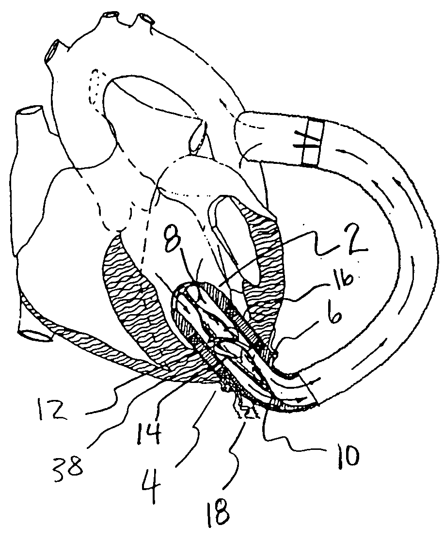
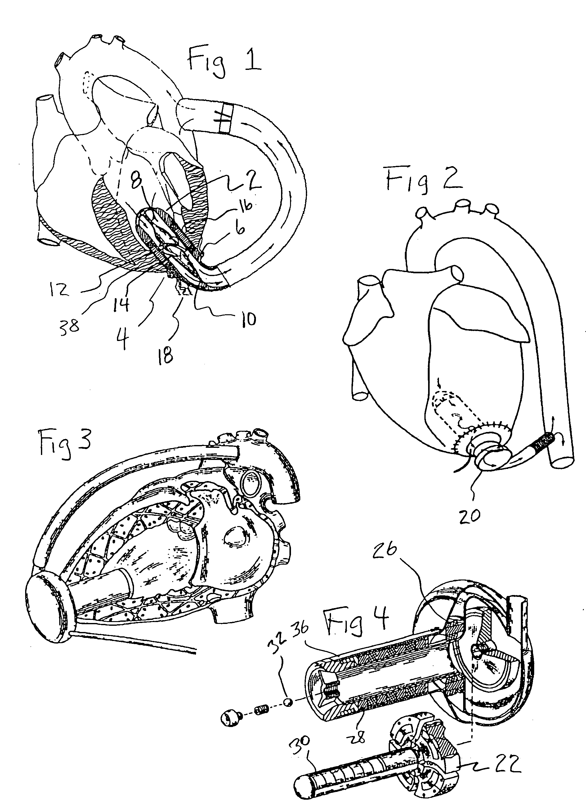
[0026]The present invention provides a thin wall “shell” which surrounds a ventricular assist device implanted in the heart. The assist device may be implanted into any of the four chambers of the natural heart. The most common position used in present clinical practice is the left ventricle, as illustrated in FIG. 1, from the prior art. An intraventricular axial flow pump 2 is positioned in the left ventricle and is implanted through a hole in the wall of the left ventricle 4, typically cut with a special instrument called a coring knife. The axial pump includes a rotor 6, supported on bearings 8, 10. The rotor supports impeller blades 12, 14. The armature of a motor, 16, receives electric power via a cable, 18. Properly timed power pulses induce magnetic fields in the motor armature which apply magnetic force to magnets within the rotor. The blood pumping device may be substantially implanted inside the heart, as in the prior art embodiment of FIG. 1, or it may utilize some elemen...


PUM


Abstract

The blood contacting surfaces of heart assist devices must avoid excessive thrombus formation, which can break off and cause thromboembolism, become infected and cause other problems. Certain textured surface coatings, such as sintered titanium microsphere coatings, form a thin layer of living cells on the surface that becomes endothelized and is highly resistant to thrombus generation. Some of these coatings require high processing temperatures. Simple thick wall conduit tubes, which do not require high precision, coated with sintered microspheres, have been used successfully as inlet cannulae. Thick wall titanium pump components have also been successfully coated with sintered microspheres, using methods to retain their shape in the furnace and avoid excessive deformation. Blood pumps or portions of blood pumps that utilize high precision components subject to damage or warping if exposed to high temperatures cannot be directly coated. This applies to intraventricular and other blood pumps with precision heat sensitive components, such as polymer insulated wires, placed at least partly within an organ of the cardiovascular vascular system. The present invention provides a thin wall textured surface shell that is coated at high temperature and then, after finish machining, is affixed over the heat sensitive precision blood pump to serve as the interface with biological tissues.

Description

BACKGROUND OF THE INVENTION[0001]In recent years ventricular assist devices used to support the pumping function of the natural heart have become increasingly successful. Long term patient survival in excess of five years has been achieved and many developers of ventricular assist devices are working on improved models intended to sustain patients in excess of a decade. Attachment of the blood pump is usually made by placement of an inlet cannula into the apex of the left ventricle. Alternatively, a cannula may be placed into the left atrium, right ventricle or right atrium. In some cases, blood pumps may be placed directly within the heart, such as the Jarvik 2000 device, U.S. Pat. No. 5,613,935, or some components of the device may be placed within the ventricle while other components are immediately adjacent to the heart, such as the hybrid flow pump of U.S. Pat. No. 5,824,070 or the rotary pump of U.S. Pat. No. 6,234,998 by Wampler.[0002]It is important to establish a stable tis...

Claims


Application Information

Patent Timeline
Patent Type & Authority Applications(United States)
IPC IPC(8): A61N1/362A61M60/178A61M60/221A61M60/232A61M60/237A61M60/422A61M60/81
CPCA61L33/022A61M1/122A61M1/101A61M60/422A61M2207/00A61M60/81A61M60/232A61M60/237A61M60/178A61M60/221A61M60/861A61M60/863A61M60/148
Inventor JARVIK, ROBERT
Owner JARVIK ROBERT
Why Eureka
Try Eureka