Electric Double Layer Capacitor

a double-layer capacitor and capacitor technology, applied in the field of electric double-layer capacitors, can solve the problems of not meeting the requirements for a size reduction, using the same capacitor, and the device cannot handle such an instantaneous large current discharge very well

Inactive Publication Date: 2008-04-17
TEIJIN LTD
View PDF3 Cites 48 Cited by
  • Summary
  • Abstract
  • Description
  • Claims
  • Application Information

AI Technical Summary

Problems solved by technology

No one skilled in the art would deny the effectiveness of the capacitor / cell combination, but using the capacitor of the same volume as that of the battery in order to absorb the large current load is difficult in practice, because then the volume of the power supply would significantly increase; there has therefore developed a need for capacitors having a power output five to ten or more times greater than that of the current ones.
However, Tokuhyou No. 2002-532869 does not disclose information about the energy density of the capacitor, and therefore does not satisfy the requirements for a size reduction required of the capacitor.
However, high-capacity batteries, such as lithium-ion batteries and nickel-hydrogen batteries, currently employed in these portable devices cannot handle such an instantaneous large current discharge very well, and there have arisen problems such as shortened service life due to an abrupt drop in battery voltage associated with such an instantaneous large current and to chemical deterioration associated with rapid electrochemical reactions; in view of this, a capacitor having a high power output characteristic capable of such an instantaneous large current discharge is being considered for use in combination with the battery.
However, the reality is that no capacitors so far developed satisfy the above stated requirements that the capacitor have a size and shape that can comfortably fit in a generally restricted, high-density mounting space within a portable device, and that the capacitor have a high power output characteristic and also have a sufficiently high energy density that can fulfill the various requirements of such a portable device battery.
The nonaqueous-type electric double layer capacitor has the advantage that the breakdown voltage of the electrolytic solution is high and the energy density is high, but the disadvantage is that its output is inferior to that of the aqueous-type electric double layer capacitor because the ion conductivity of the electrolytic solution is low.
When the high output is achieved by such techniques, the volume that the separator and current collectors occupy within the cell increases, and this cannot always be said to be desirable from the standpoint of energy density and cost.
While the above prior art uses relatively fine activated carbon, the contribution of the fine activated carbon to the increased output is not clear, because the electrode thickness is extremely small.
The reason for this may be that when fine activated carbon is used, it becomes extremely difficult to form an electrode layer on the current collector and, as a consequence, it has only been possible to fabricate an extremely thin electrode.
This is because, as the thickness of the separator decreases, failure occurs more easily due to an electrical short between the anode and cathode and, considering quality assurance in the mass-production of capacitors, it is practically difficult to reduce the thickness of the separator.
However, at low temperatures, the diffusion of the electrolyte in the electrolytic solution is hindered, and the diffusion resistance of the impedance increases, resulting in the problem that the output characteristic of the electric double layer capacitor is significantly degraded.
This has been a major factor limiting the range of applications of the electric double layer capacitor.
As a method of solution, one could easily conceive of increasing the pore size of the porous carbon material used as the electrode material; however, in this case, since a sufficient per-volume electric capacity cannot be obtained, the intended purpose of the capacitor is defeated.

Method used


Image

  • Electric Double Layer Capacitor
  • Electric Double Layer Capacitor
  • Electric Double Layer Capacitor

Examples


embodiment 1

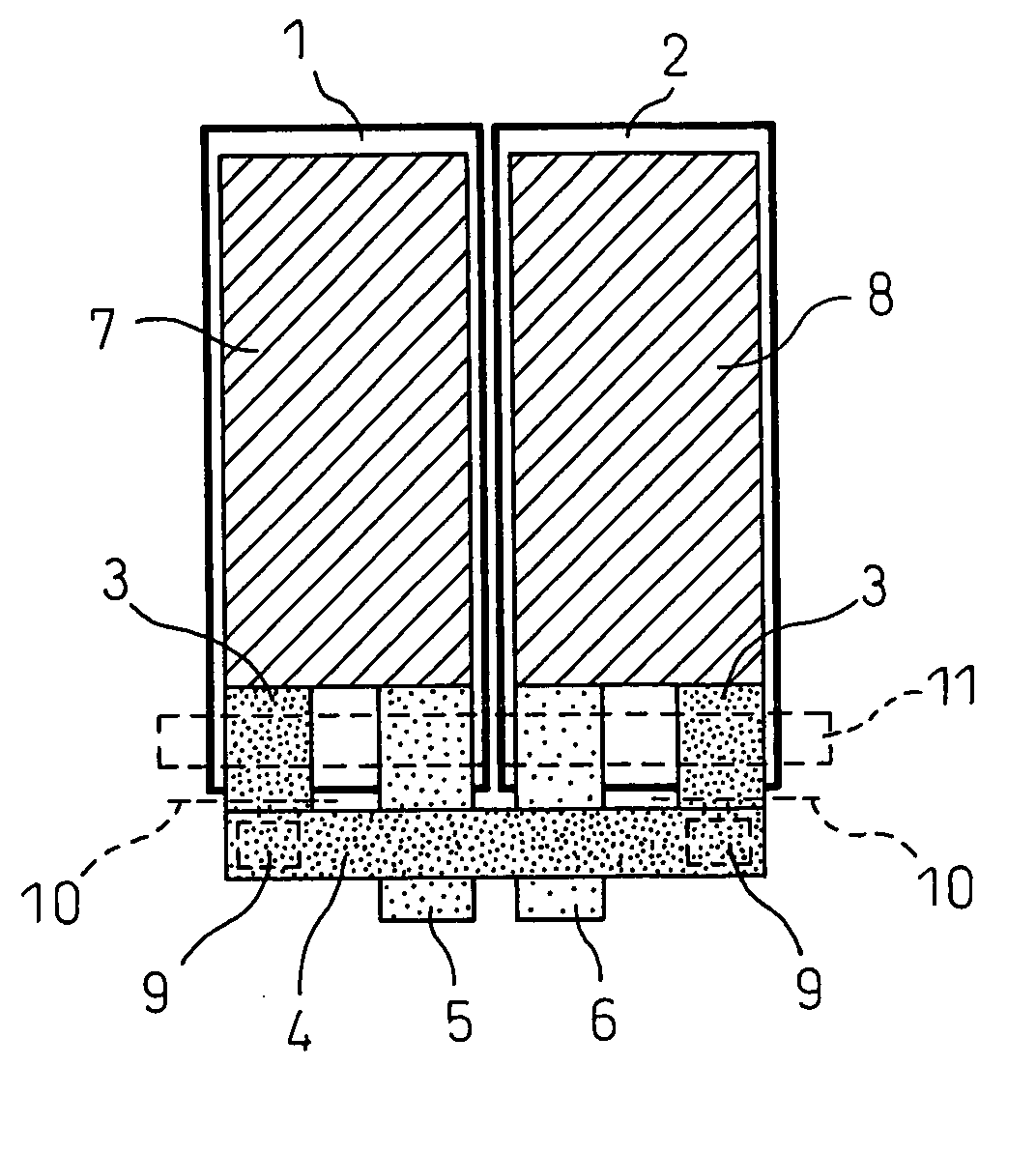
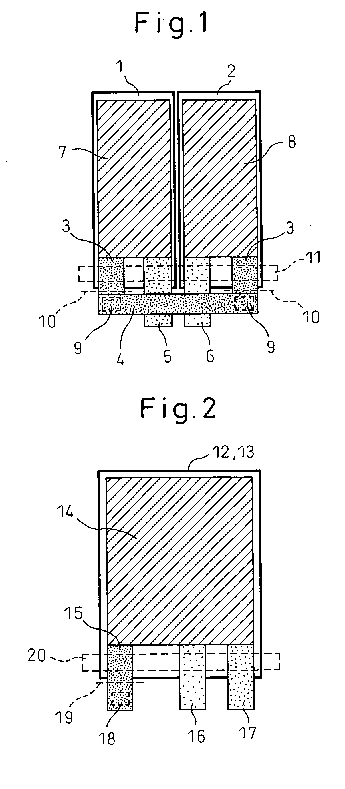
[0043] An electric double layer capacitor according to a first embodiment achieves a higher power output, especially a higher power output under low-temperature environments, than the conventional electric double layer capacitor. Accordingly, the electric double layer capacitor of this embodiment is useful in applications that impose stringent requirements on the operating characteristics under low-temperature environments, and more specifically, in hybrid electric vehicle (HEV) and like applications.

[0044] In the first embodiment, the electric double layer capacitor comprises a pair of electrodes formed from activated carbon, a separator, and a nonaqueous electrolytic solution, and is characterized in that the average particle size of the activated carbon is not smaller than 0.1 μm but smaller than 1.0 μm. In the following description, the activated carbon used in the electric double layer capacitor of the present invention is called the submicron activated carbon. The average par...

example 8

Method Example 8

[0110] 93 parts by weight of the experimental activated carbon 1, 7 parts by weight of acetylene black, 17 parts by weight of polyvinylidene fluoride (manufactured by Kureha Chemical), 337 parts by weight of DMAc, and 4 parts by weight of polyvinyl pyrrolidone were mixed to produce a slurry. The slurry was applied over the experimental current collector 3 and dried. The structure was then pressed at a temperature of 150° C. to produce an activated carbon electrode.

Reference Method Example 1

[0111] 93 parts by weight of the experimental activated carbon 1, 7 parts by weight of Ketjen black, 17 parts by weight of polyvinylidene fluoride (manufactured by Kureha Chemical), 565 parts by weight of DMAc, and 4 parts by weight of polyvinyl pyrrolidone were mixed to produce a slurry. The slurry was applied over a current collector formed from a 20-μm thick, etched aluminum foil (part number 20 CB manufactured by Japan Capacitor Industrial Company), and was dried, but cracks ...

example 4

Reference Method Example 4

[0114] 93 parts by weight of the experimental activated carbon 1, 7 parts by weight of Ketjen black, 17 parts by weight of polyvinylidene fluoride (manufactured by Kureha Chemical), and 2000 parts by weight of DMAc were mixed to produce a slurry, but the resultant slurry lacked fluidity and was unsuitable for coating. The slurry was applied over the experimental current collector 1, resulting in the production of an electrode having insufficient surface smoothness because of the formation of conspicuous surface irregularities.


PUM


Abstract

The present invention concerns an electric double layer capacitor, wherein to increase capacitance, each electrode is formed from activated carbon having an average particle size of 0.1 to 1.0 μm. Alternatively, to prevent electrode short-circuiting, each electrode is constructed from an electrode layer sheet having an electrode layer formed from activated carbon whose specific area is 500 to 2500 m2 / g and whose cumulative particle size (D90) is 0.8 to 6 μm.

Description

TECHNICAL FIELD [0001] The present invention relates to an electric double layer capacitor comprising a pair of electrodes forming an anode and cathode, a separator, and an electrolytic solution, and more particularly to an electric double layer capacitor that has a high power output characteristic and a high capacitance density or that is small and ultra-thin and yet has a high power output characteristic and a high capacitance density. [0002] Even more particularly, the invention relates to an electric double layer capacitor that comprises a pair of electrode sheets forming an anode and cathode, a separator, and a nonaqueous electrolytic solution, and that can achieve a high power output even under low-temperature environments, and also relates to an electric double layer capacitor that uses polarizable electrodes formed from a porous carbon material. BACKGROUND ART [0003] Capacitors, such as electric double layer capacitors using polarizable electrodes made of activated carbon an...

Claims


Application Information

Patent Timeline
Patent Type & Authority Applications(United States)
IPC IPC(8): H01G9/00H01G11/66H01G11/00H01G11/22H01G11/42H01G11/52H01G11/68H01G11/70H01G11/78H01G15/00
CPCH01G9/08Y02T10/7022Y02E60/13H01G9/155H01G11/24H01G11/28H01G11/38H01G11/82Y02T10/70H01G11/32
Inventor KON, TATSUICHIROSADANOBU, JIRONISHIKAWA, SATOSHISANO, HIROKISAKURAI, HIROSHIKITAHARA, MAI
Owner TEIJIN LTD
Why Eureka
Try Eureka