Tomography by Emission of Positrons (Pet) System

a positron emission and tomography technology, applied in the field of x-ray radiography and ultrasonography, can solve the problems of high cost for the society, unsatisfactory performance of conventional x-ray mammography, and not always easy to establish

Inactive Publication Date: 2008-05-01
FFCUL BEB FUNDACAO DA FACULDADE DE CIENCIAS DA UNIV DE LISBOA INST +6
View PDF3 Cites 75 Cited by
  • Summary
  • Abstract
  • Description
  • Claims
  • Application Information

AI Technical Summary

Benefits of technology

[0059]The partial-body PET of this innovation allows for an easy integration with a digital Computer Tomography (CT) sys...

Problems solved by technology

Unfortunately the performance of conventional X-ray mammography is unsatisfactory.
A large number of unnecessary biopsies or even axillary's dissections are therefore performed which have a high cost for the society, not considering the psychological aspect on the women.
The correlation between denser regions and cancer tumors is not always easy to establish, moreover cancer is very often characterized by low contrast structures in the domain of low energy X-rays, which leads to low sensitivity.
The high rate of false positive leads to a large number of unnecessary biopsies: 60 to 85% of the biopsies following an imaging indication, obtained with X-rays or ultrasounds, do not correspond to malign pathology [L. P. Adler, Beast Imaging Conference, Rome, May 2000].
More dramatic is the too large number of false negative with often fatal consequences for the patient.
Other approaches, like MRI (Magnetic Resonance Imaging) and echography have not proven yet to be more efficient than X-rays.
Moreover whole body PET systems are expensive and bulky.
The detector geometry should aim at solid angle coverage as large as possible, although some limitations are imposed by image reconstruction considerations as well as by the specifics of the human body anatomy and examination practice.
Parallax effect is an important issue especially when planar detectors located close to the object under examination are used.
On the other hand, the detector will be subject to a large photon flux from decays occurring in the whole body.
However the ...

Method used


Image

  • Tomography by Emission of Positrons (Pet) System
  • Tomography by Emission of Positrons (Pet) System
  • Tomography by Emission of Positrons (Pet) System

Examples


Embodiment Construction

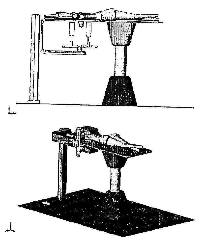
[0084]This chapter describes a complete PET imaging system dedicated to exams of body parts such as the breast, axilla, head, neck, liver, heart, lungs, prostate region, and other extremities. The imaging system may also be used to make PET exams of small animals. One of the main characteristics of the present system is how different innovative aspects are combined and articulated to provide improved PET imaging performance in relation to previous systems or proposals.

[0085]5.1 The Partial-Body PET System

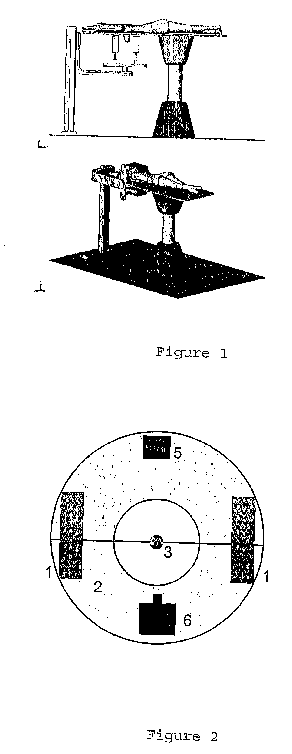
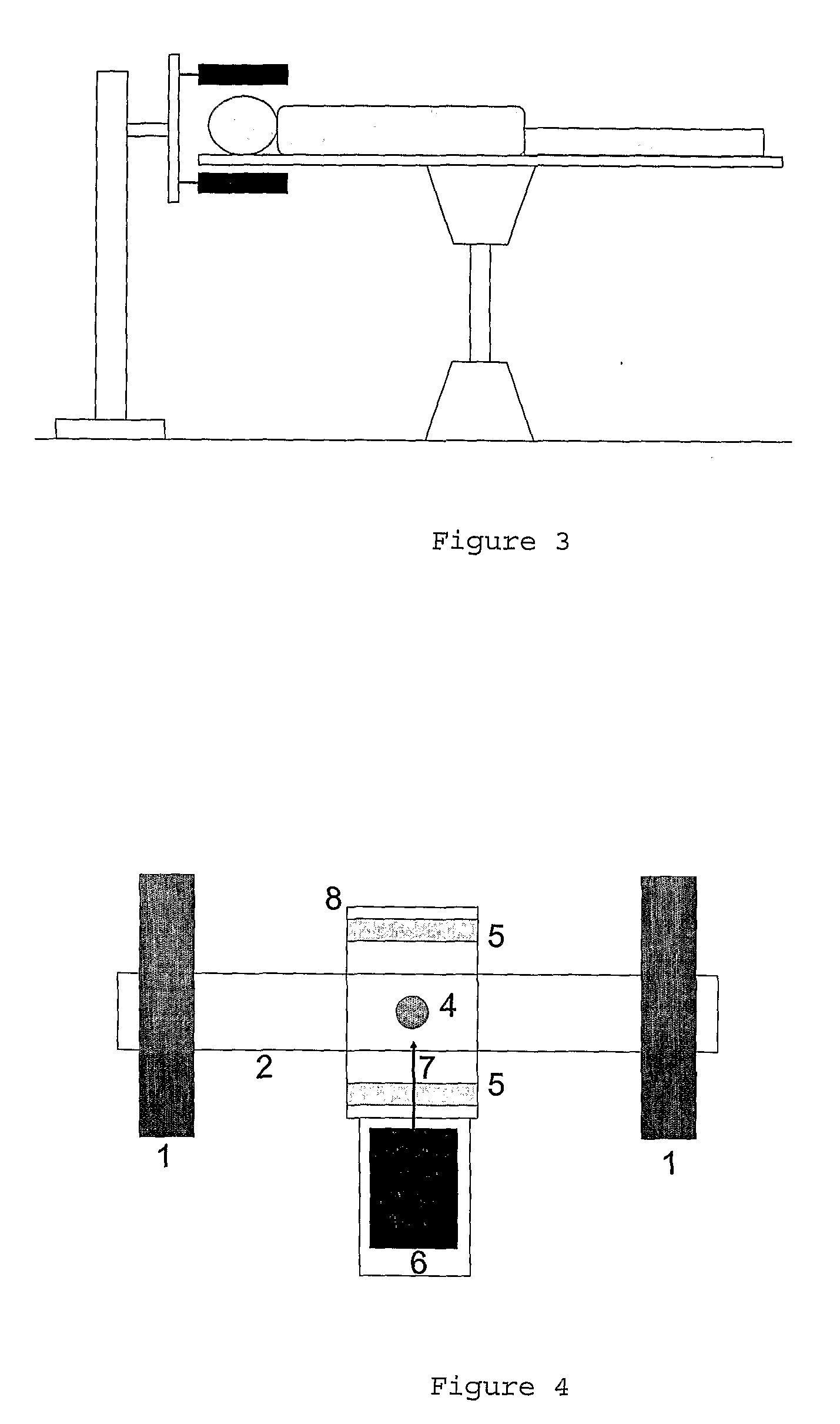
Device Configuration

[0086]The partial-body PET system has the following geometrical configuration:[0087]a) The PET detector is formed by two or more detecting plates (detector heads) with dimensions that are optimized for the breast, axilla region, brain and prostate region.[0088]b) The plates are able to rotate around the PET axis, under computer control, allowing taking data in several orientations as needed for tomographic image reconstruction.[0089]c) The PET detector system can...


PUM


Abstract

Tomography by emission of positrons (pet) system dedicated to examinations of human body parts such as the breast, axilla, head, neck, liver, heart, lungs, prostate region and other body extremities which is composed of at least two detecting plates (detector heads) with dimensions that are optimized for the breast, axilla region, brain and prostrate region or other extremities; motorized mechanical means to allow the movement of the plates under manual or computer control, making it possible to collect data in several orientations as needed for tomographic image reconstruction; an electronics system composed by a front-end electronics system, located physically on the detector heads, and a trigger and data acquisition system located off-detector in an electronic crate; a data acquisition and control software; and an image reconstruction and analysis software that allows reconstructing, visualizing and analyzing the data produced during the examination.

Description

1. BACKGROUND OF THE INVENTION[0001]For a long time, medical imaging was mainly based on the physical principles of X-Ray Radiography and ultrasonography. The progress on these two techniques occurred mainly at the level of image detection, software for image processing and data storing. Recently, other techniques, based on different physical mechanisms, gave to the field of medical imaging new horizons on the exploration of human body's morphology and functionality.[0002]A recent example is Positron Emission Tomography, PET, mainly used on cancer detection, with proved effective cost-benefit in cancer detection, staging and evaluation of therapy efficacy. The underlying principle of PET systems, as any other nuclear medicine method, is the detection of gamma radiation from a radioactive substance injected into the human body. In PET, the radioactive substance includes radioisotopes of atoms existing in biological molecules and so, with more affinity to certain biochemical mechanism...

Claims


Application Information

Patent Timeline
IPC IPC(8): G01T1/164A61B6/03
CPCG01T1/1615G01T1/2985A61B6/583A61B6/037A61B6/508G01T1/2008
Inventor DOS SANTOS VARELA JOAO MANUEL COELHO
Owner FFCUL BEB FUNDACAO DA FACULDADE DE CIENCIAS DA UNIV DE LISBOA INST
Why Eureka
Try Eureka