Porous Anode Body For Solid Electrolytic Capacitor, Production Method Thereof and Solid Electrolytic Capacitor

a technology of porous anodes and solid electrolytic capacitors, which is applied in the direction of electrolytic capacitors, liquid electrolytic capacitors, transportation and packaging, etc., can solve the problems of insufficient impurity impregnation of solid electrolyte into small pores, inability to form uniform pores, and inability to produce uniform pores. , to achieve the effect of low esr, good tan characteristics, and high capacitan

Inactive Publication Date: 2008-05-08
SHOWA DENKO KK
View PDF36 Cites 33 Cited by
  • Summary
  • Abstract
  • Description
  • Claims
  • Application Information

AI Technical Summary

Benefits of technology

[0010]An object of the present invention is to provide: a method of manufacturing a porous anode for a solid electrolytic capacitor having a pore distribution being controlled within the range suitable for impregnating a cathode agent, which enables prod

Problems solved by technology

In this case, however, a minute primary powder may inevitably create small pores.
In particular, in the case of a large porous anode having a volume of 10 mm3 or more in which the distance from the surface to the deep part is long, solid electrolyte can not be sufficiently impregnated into small pores.
Moreover, there is another problem that uniform pores cannot be formed owing to variation in pore size.
However, each of those manufacturing methods intends to control the oxygen amount withou

Method used


Image

  • Porous Anode Body For Solid Electrolytic Capacitor, Production Method Thereof and Solid Electrolytic Capacitor
  • Porous Anode Body For Solid Electrolytic Capacitor, Production Method Thereof and Solid Electrolytic Capacitor
  • Porous Anode Body For Solid Electrolytic Capacitor, Production Method Thereof and Solid Electrolytic Capacitor

Examples


example 1

[0133]A mixture powder having an average particle size of 120 μm, which contains 80 parts by mass of niobium powder having an average particle size of 0.5 μm, containing 12% by mass of oxygen; 10 parts by mass of calcium oxide having an average particle size of 0.9 μm; and 10 parts by mass of calcium oxide having an average particle size of 2 μm, was prepared.

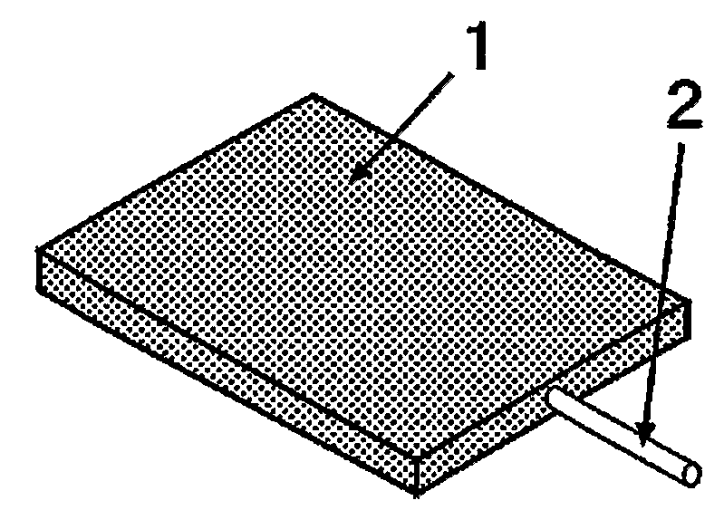
[0134]In a solution prepared by dissolving 40 g of camphor into 1 litter of toluene, 900 ml of the mixture powder having an average particle size of 120 μm and 100 ml of calcium oxide having an average particle size of 30 μm were added and mixed well. Then, toluene was distilled off at about 60° C. under reduced pressure of about 1×10² Pa, thereby obtaining a mixture powder containing niobium, calcium oxide, and camphor. Furthermore, this mixture powder was automatically molded together with a niobium wire of 0.3 mm in diameter so as to be one approximately measuring 3.3 mm×1.8 mm×4.3 mm (about 25 mm3). The niobium-corrected de...

example 2

[0138]A mixture powder having an average particle size of 90 μm, which contains 70 parts by mass of niobium powder having an average particle size of 0.5 μm, containing 15% by mass of oxygen; 15 parts by mass of barium oxide having an average particle size of 0.7 μm; and 15 parts by mass of barium oxide having an average particle size of 2 μm, was prepared.

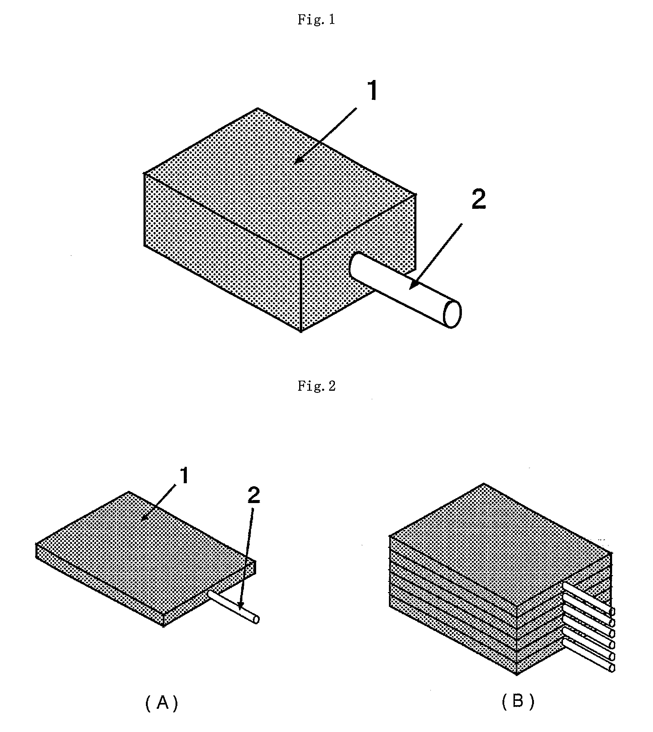
[0139]In a solution prepared by dissolving 40 g of camphor into 1 litter of toluene, 900 ml of the mixture powder having an average particle size of 90 μm and 100 ml of barium oxide having an average particle size of 20 μm were added and mixed well. Then, toluene was distilled off at about 60° C. under reduced pressure of about 1×10² Pa, thereby obtaining a mixture powder containing niobium, barium oxide, and camphor. Furthermore, this mixture powder was automatically molded together with a niobium wire of 0.20 mm in diameter so as to be one approximately measuring 0.4 mm×1.8 mm×4.3 mm (about 3.1 mm3). The niobium-corrected densit...

example 3

[0145]A mixture powder which contains 90 parts by mass of niobium powder having an average particle size of 0.5 μm, containing 9% by mass of oxygen; 6 parts by mass of magnesium hydroxide having an average particle size of 0.7 μm; and 10 parts by mass of magnesium hydroxide having an average particle size of 2 μm, was prepared.

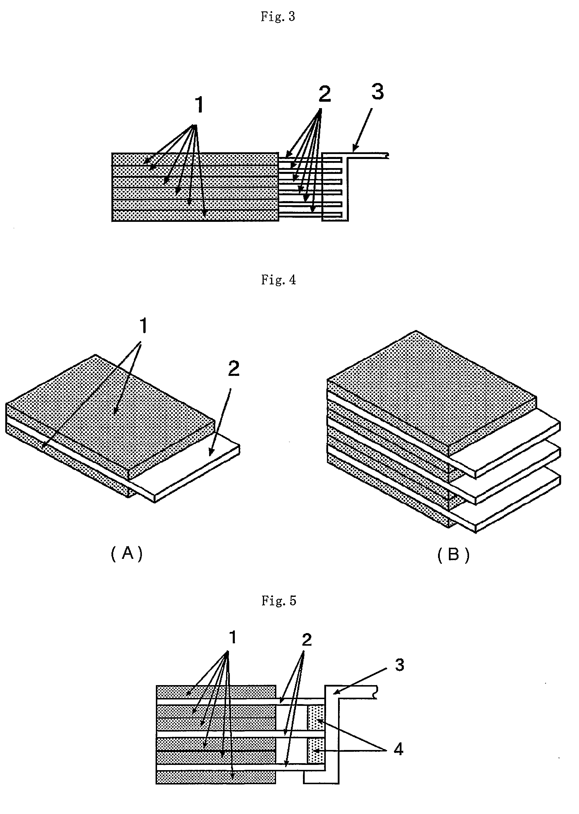
[0146]A slurry liquid was prepared by adding 900 ml of a mixture powder having an average particle size of 90 μm and 100 ml of magnesium hydroxide having an average particle size of 10 μm to a solution prepared by dissolving 40 g of camphor in 1 litter of toluene and stirring the mixture well. Next, a mask having a thickness of 0.2 mm and having a plurality of openings in a lattice-like pattern for the formation of a powder-sintering layer of 3.3 mm×4.3 mm was mounted on a niobium foil having a thickness of 50 μm. Subsequently, the slurry liquid was applied onto the surface of the lattice-shaped mask while being discharged from a die-coating mold attached on t...


PUM

PropertyMeasurementUnit
Temperatureaaaaaaaaaa

Abstract

The invention provides a method of manufacturing a porous anode for a solid electrolytic capacitor, comprising a step of subjecting a molded body containing powder of at least one material selected from oxygen-containing niobium material and oxygen-containing tantalum material and a pore-forming agent which is solid at reduction temperature to reduction reaction using reducing agent and another step of removing the pore-forming agent from the reduction reaction product and a solid electrolytic capacitor using an anode obtained thereby. As niobium material and tantalum material, at least one material selected from niobium, niobium alloy, niobium compound, tantalum, tantalum alloy and tantalum compound is used respectively. In the invention, the peak position, the number and quantity of pores can be optimized according to the cathode agent used, whereby a solid electrolytic capacitor having an improved property for impregnation with cathode agent, high capacitance, low ESR, good tan δ characteristics and long-term reliability, is obtained.

Description

CROSS-REFERENCE TO RELATED APPLICATIONS[0001]This is an application filed pursuant to 35 U.S.C. Section 111(a) with claiming the benefit of U.S. provisional application Ser. No. 60 / 633,119 filed Dec. 6, 2004 under the provision of 35 U.S.C. 111(b), pursuant to 35 U.S.C. Section 119(e)(1).TECHNICAL FIELD[0002]The present invention relates to a method of manufacturing a niobium- or tantalum-based porous anode for a solid electrolytic capacitor, which method is capable of adjusting a pore distribution (peak position of diameter, average pore diameter, and pore volume) to be suitable for impregnating a cathode agent and capable of easily controlling the oxygen amount. In addition, the present invention relates to a solid electrolytic capacitor using a niobium- or tantalum-based porous anode obtained by that method, having excellent high capacitance, low ESR, and excellent tan δ characteristics, as well as long-term reliability.BACKGROUND ART[0003]Small-sized capacitors having large capa...

Claims


Application Information

Patent Timeline
IPC IPC(8): H01G9/048C22B5/00B22F3/11
CPCH01G9/042Y10T428/12014Y10T29/417H01G9/052
Inventor AMITA, HITOSHIOMORI, KAZUHIRO
Owner SHOWA DENKO KK
Why Eureka
Try Eureka