Apparatus and method for increasing the concentration of recycled hydrogen in a high pressure hydrogenation reactor

a technology of high-pressure hydrogenation and apparatus, which is applied in the direction of hydrogen separation using liquid contact, separation process, physical/chemical process catalyst, etc., can solve the problems of reducing the equipment investment of the whole reaction system comprising reactor(s), reducing the purity of recycle hydrogen, and reducing the total reacting pressure. , to achieve the effect of reducing the pressure of concentration-increased hydrogen, reducing the total reacting pressure, and high pressur

Active Publication Date: 2008-05-15
PETROCHINA CO LTD +1
View PDF6 Cites 6 Cited by
  • Summary
  • Abstract
  • Description
  • Claims
  • Application Information

AI Technical Summary

Benefits of technology

[0005] The object of the present invention is, taking advantages of the hydration method, namely, to fit high pressure operation and not substantially decreasing the pressure of the concentration-increased hydrogen, to increase the concentration of the recycle hydrogen in middle and high pressure hydrogenation units and lower the total reacting pressure so as to cut down

Problems solved by technology

Light hydrocarbon components, methane for example, which are produced during the process of hydrogenation, may be accumulated and thus decrease the purity of recycle hydrogen as they cannot be effectively separated from the recycle hydrogen in the high-pressure separator.
In the case that the partial pressure of hydrogen needed by the reaction is fixed, the increase of the concentration of hydrogen can decrease the whole reacting pressure and therefore lower the equipment investment of the whole reaction system comprising reactor(s), heating oven(s), heat exchanger(s), cooler(s), high pressure separator(s) and pipes & lines, etc.
After the concentration of recycle hydrogen is increased and the total operating pressure of the hydrogenation reactor is

Method used


Image

  • Apparatus and method for increasing the concentration of recycled hydrogen in a high pressure hydrogenation reactor
  • Apparatus and method for increasing the concentration of recycled hydrogen in a high pressure hydrogenation reactor
  • Apparatus and method for increasing the concentration of recycled hydrogen in a high pressure hydrogenation reactor

Examples


example 1

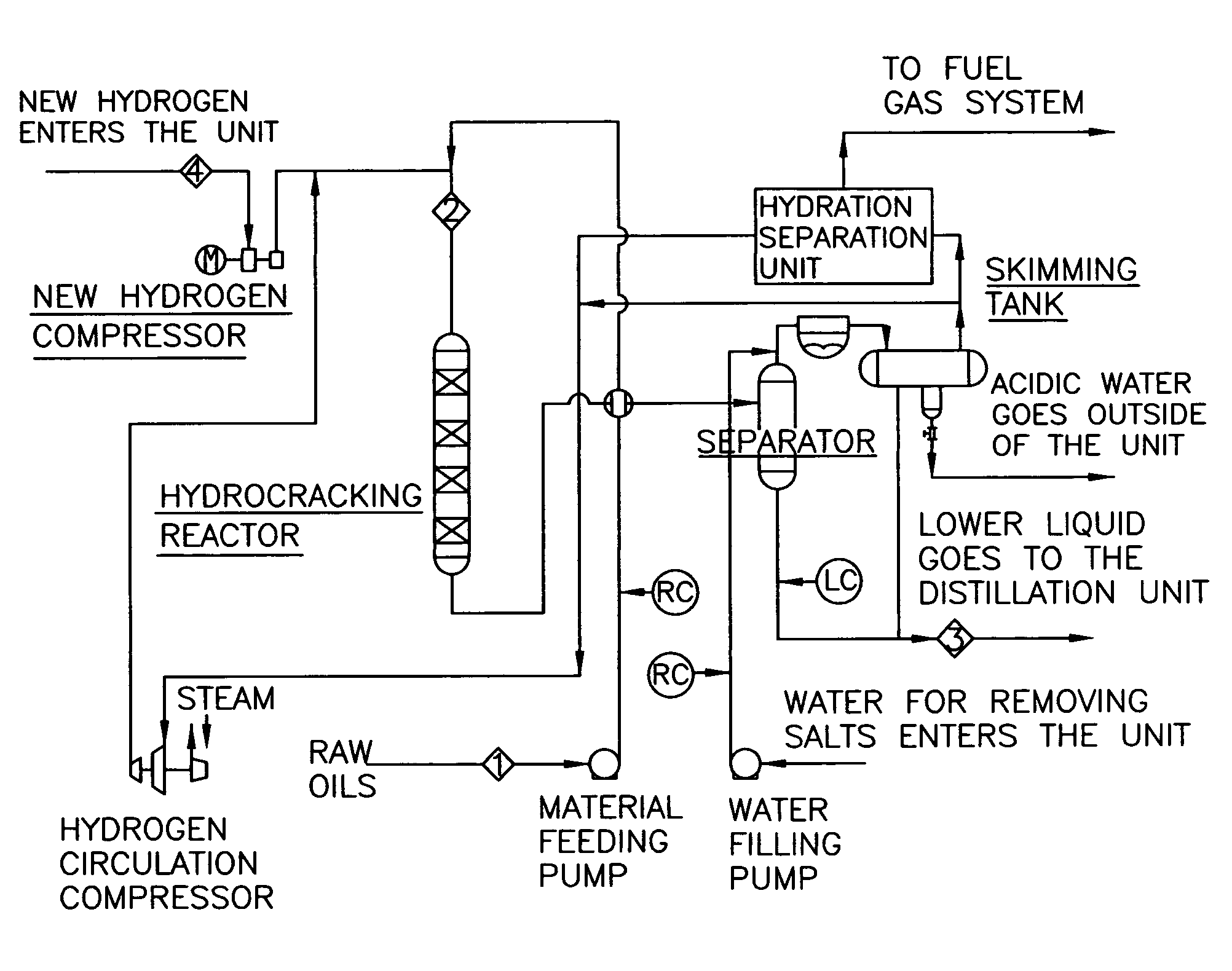
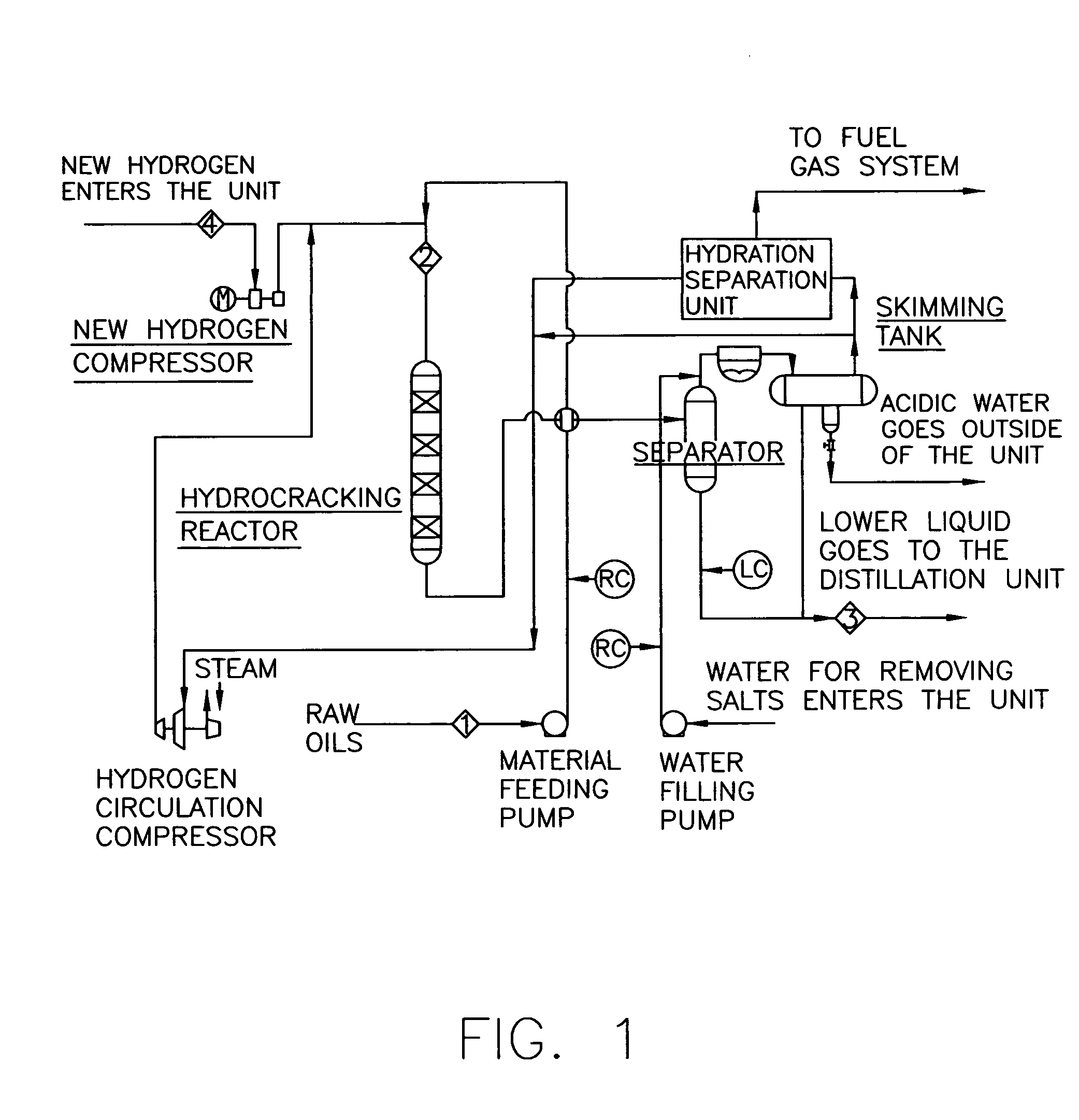
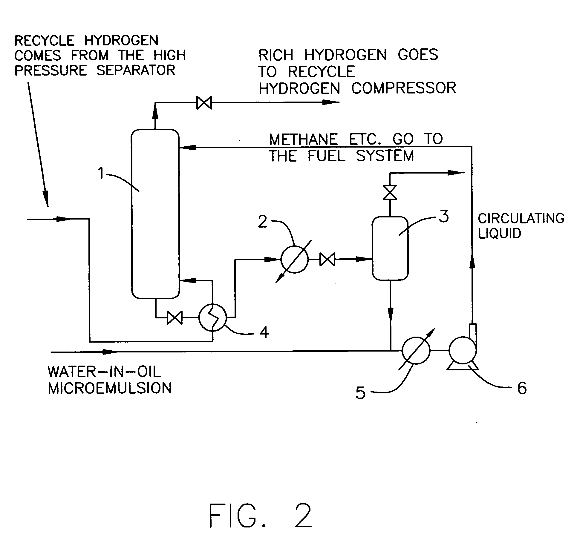
[0070] Between a high-pressure separator and a hydrocracking reactor a hydration separation unit comprising a hydration reactor 1 and a hydrate decomposer 3 was included. The hydration reactor 1 was constructed with the combination of a mist spray and sieve plates. The upper part of the reactor was the mist spray area equipped with sprayers 13 and a set of serpentine cooling pipes 9. The lower part of the reactor was the sieve plates area equipped with sieve plates 10. The internal upper part of the hydrate decomposer 3 was equipped with wire mesh demisters 15. A high pressure separator was connected with the inlet 11 of raw gases at the lower part of the sieve plates area of the hydration reactor via heat exchanger 4; the outlet 12 of hydrate slurry at the bottom of the hydration reactor was connected with the inlet 17 of hydrate slurry of the hydrate decomposer via heat exchanger 2; the outlet 7 of hydrogen with high concentration (rich hydrogen) at the top of the hydration reacto...

example 2

[0072] The same equipments are employed as in example 1 except that

[0073] The composition of raw gases entering into the hydration separation unit (equivalent to the gases from the high pressure separator) was: H2 (93 mol %)+CH4(5 mol %)+C2H6 (2 mol %). The operating temperature of the hydration reactor was 1-5° C. with 18 MPa of the operating pressure. The water-in-oil microemulsion was prepared with 3 volumes of water solution in which the mass concentration of tetrahydrofuran was 21% by mass and 7 volumes of diesel, the microemulsion / gas flux ratio was 1 / 100 (standard V / V), and the gases stayed in the reactor for 18 minutes. After the concentration of hydrogen was increased, the gases contained H2 (97.5 mol %)+CH4(2.2 mol %)+C2H6(0.3 mol %). The concentration of hydrogen in the mixture of concentration-increased gases and raw gases (mixed in the volume ratio of 1:1) showed 95.2%, indicating that of the gases coming from the high pressure separator, mixing of 50% which had experi...

example 3

[0074] The same equipments are employed as those in example 1 except that:

[0075] The composition of raw gases entering into the hydration separation unit (equivalent to the gases from the high pressure separator) was: H2 (90 mol %)+CH4(7 mol %)+C2H6 (3 mol %). The operating temperature of the hydration reactor was 1-5° C., the operating pressure was 15 MPa, the water-in-oil microemulsion was prepared with 3 volumes of water solution in which the mass concentration of tetrahydrofuran was 21% by mass and 7 volumes of diesel, the microemulsion / gas flux ratio was 1 / 100 (standard V / V), and the gases were kept in the reactor for 18 minutes. After the concentration of hydrogen was increased, the gases contained: H2 (97.0 mol %)+CH4(2.5 mol %)+C2H6(0.5 mol %). The concentration of hydrogen in the mixed gases of concentration-increased gases and raw gases (mixed in the volume ratio of 5:2) was 95.0%, indicating that of the gases coming from the high pressure separator, mixing of 71% which h...


PUM

PropertyMeasurementUnit
Temperatureaaaaaaaaaa

Abstract

An apparatus and a method that increase the concentration of recycled hydrogen in the hydrogenation unit are disclosed having a hydration separation unit included between the high-pressure separator and hydrocracking reactor. A part of the recycled hydrogen contacts with the water-in-oil microemulsion to form hydrates from which the light hydrocarbon components are removed. The gas flow entering into the hydration separation unit is present in amount of 20%˜100% of the total gas flow coming from the high-pressure separator; the water-in-oil microemulsion, in which the volume ratio of oil and water is 1:1 to 5:1 may increase hydrogen partial pressure in the reactor and thus upgrade the performance of hydrogenation.

Description

RELATED APPLICATION [0001] This application claims the benefit of priority from Chinese Patent Application No. 2006 10150085.7, filed on Oct. 26, 2007, the entirety of which is incorporated herein by reference. FIELD OF THE INVENTION [0002] The present invention relates to an apparatus and a method that can, by forming hydrates, increase the concentration of recycle hydrogen in a hydrogenation reactor, so as to increase the hydrogen partial pressure in the reactor, improve the performance of hydrogenation, reduce the cost of equipment and power consumption, and avoid the problem of hydrogen purge. BACKGROUND OF THE INVENTION [0003] Hydrogen is an essential material of the hydrogenation process, especially hydrocracking process in refinery, and its purity exerts a tremendous influence on the manufacturing and operating expenses of the hydrogenation unit as well as other reaction performances including the yield of the target products and the operational cycle of catalysts. The proces...

Claims


Application Information

Patent Timeline
IPC IPC(8): B01J35/02
CPCB01D53/14B01D2256/16B01D2257/7022C01B3/506C10G49/22C01B2203/046C01B2203/048C10G47/00C10G49/007C01B3/52
Inventor CHEN, GUANGJINMA, ANYAN, LIJUNGUO, XUQIANGSUN, CHANGYUWANG, XIULIN
Owner PETROCHINA CO LTD
Why Eureka
Try Eureka