

Surface Treatment of Biomedical Devices
- Summary
- Abstract
- Description
- Claims
- Application Information
AI Technical Summary
Benefits of technology
Problems solved by technology
Method used
Image

Examples
example 1
[0086]Step I: Preparation of 2-Ethylacrylic acid.
[0087]2-Ethylacrylic acid was prepared from diethyl ethylmalonate using procedures set forth in the literature (e.g., Ferrito et al., Macromol. Synth., 11, pp. 59-62 (1992)). Diethyl ethylmalonate (100 g, 0.53 mol) was added to a 1 L round bottom flask and stirred overnight with 700 mL of 1 M KOH in 95% ethanol. The ethanol was then removed with a rotary evaporator and the residue was dissolved in a minimum amount of water and acidified to a pH of 2.0 by slow addition of concentrated HCl. The separated oil (2-carboethoxybutyric acid) was taken up into diethyl ether (3×200 mL portions of ether in a separatory funnel), dried over magnesium sulfate and concentrated on a rotary evaporator. The crude 2-carboethoxybutyric acid (84.9 g, 0.53 mol) was placed in a 1 L round bottom flask and cooled to −5° C. Diethylamine (55 mL, 0.53 mol) was then added to the flask and an addition funnel containing 43.5 g formaline solution (0.54 mol) was adde...
example 2
[0090]Step I: Preparation of 2-Propylacrylic acid.
[0091]2-Propylacrylic acid was prepared from diethyl propylmalonate by a modification of a procedure set forth in the literature (e.g., Ferrito et al., Macromol. Synth., 11, pp. 59-62 (1992)) in which diethyl propylmalonate was used instead of diethyl ethylmalonate. The procedure used was identical to that set forth in Example 1. Crude 2-propylacrylic acid (yellow oil) was vacuum distilled (b.p. 60° C. / 1 mm Hg) to yield pure, colorless 2-Propylacrylic acid (35 gm).
[0092]Step II: Preparation of Poly(2-propylacrylic acid).
[0093]Distilled 2-Propylacrylic acid was placed in ampules and subjected to four freeze-degas-thaw cycles and sealed under vacuum. AIBN (from 0.1-5 mol %) was added and the polymerizations were carried out in bulk at 64° C. for 24 hours. The resulting slurry was dissolved in methanol and precipitated into diethyl ether. The precipitated polymer was collected by filtration, dissolved in pH 10 phosphate buffer, and dial...
example 3
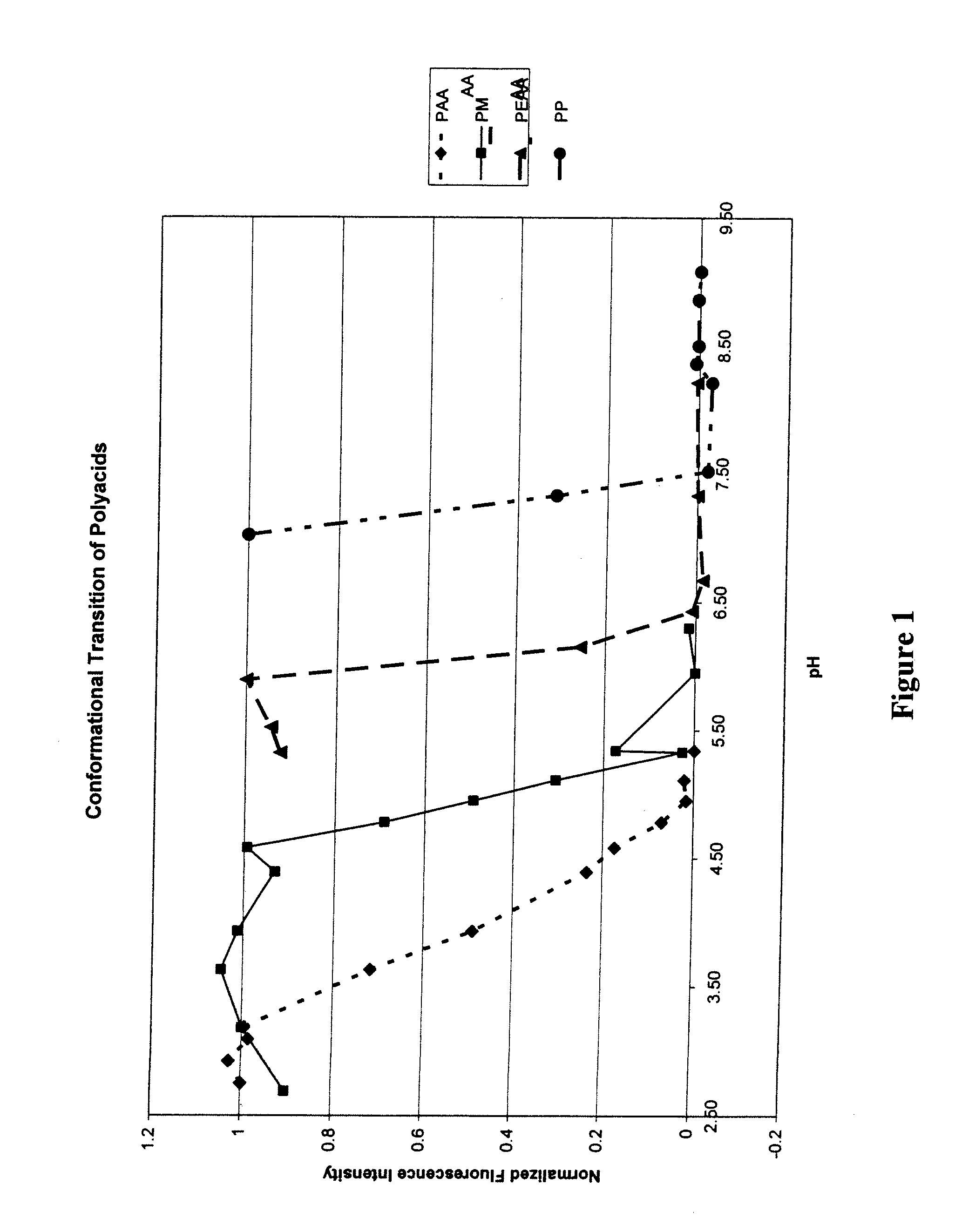
[0094]Conformational Properties of Poly(carboxylic acid)s.
[0095]The conformational transition of a series of poly(carboxylic acid)s in solution was studied by observing the steady-state fluorescence of codissolved pyrene using procedures set forth in the literature (e.g., Chen et al., J. Polym. Sci. Polym. Chem., 17, pp. 1103-1116 (1979)). In this study, a polymer stock solution of low buffer capacity was prepared by dissolving the poly(carboxylic acid) (4 mg / ml) and pyrene (200 μM) in a 5 mM buffer (phosphate or borate) of high enough pH for dissolution. Buffers of higher buffer capacity (100 mM) were prepared ranging in pH from 2.2 to 10.0 using either citric acid-phosphate, sodium and disodium phosphate, or boric acid-borax buffering systems. Samples for fluorescence measurements were prepared by mixing 0.5 ml of the polymer / pyrene stock solution with 1.5 ml of the higher buffer capacity solutions at various solution pH, to give final concentrations of 1 mg / mL of the poly(carboxy...
PUM
| Property | Measurement | Unit |
|---|---|---|
| Molality | aaaaa | aaaaa |
| Hydrophilicity | aaaaa | aaaaa |
| Wettability | aaaaa | aaaaa |
Abstract
Description
Claims
Application Information