UV flux multiplication system for sterilizing air, medical devices and other materials

a technology of uv flux and sterilization system, which is applied in the direction of lighting and heating apparatus, heating types, instruments, etc., can solve the problems of reducing the effectiveness of homogeneous distribution of photons within the irradiation chamber, increasing power consumption, and reducing so as to reduce the size of the air duct sterilization system, reduce the number of lamps required, and reduce the effect of power requirements

Active Publication Date: 2008-06-26
NOVATRON
View PDF16 Cites 44 Cited by
  • Summary
  • Abstract
  • Description
  • Claims
  • Application Information

AI Technical Summary

Benefits of technology

[0009]The invention described herein provides for a reduction in power requirements of a factor of over 100 compare to the Wick et al results. In one example, it is shown that the power required to kill spores to a level of 99.9999% is on the order of 1,500 watts, at a flow rate of 10,000 cubic feet per minute (cfm.), or about the same as the requireme...

Problems solved by technology

When reflectors restrict the flow of air they create a pressure drop in the flow which increases power consumption.
The openings for flow also reduce effectiveness by allowing light t...

Method used


Image

  • UV flux multiplication system for sterilizing air, medical devices and other materials
  • UV flux multiplication system for sterilizing air, medical devices and other materials
  • UV flux multiplication system for sterilizing air, medical devices and other materials

Examples


example 1

Parallelepiped Sterilization Chamber with Moveable Flaps at the Inlet and Exit Ends using a Pulsed Light Source with 30% of Total Fluence Between 200-300 nm

[0077]

Air flow rate (cubic meters / second)Q = 1,141,600 cm3 / secAverage air flow velocityVave = 274.3 cm / secPeak air flow velocityvmax = 362.7 cm / secDimensions of chamberH = 50.8 cmW = 101.6 cmL = 304.8 cmTotal inner surface areaA = 103,225 cm2Area of EndsAE = 10,320 cm2Percentage of ends open to flowPOE = 2%Open area of EndsAOE = 206 cm2Number of lampsNL = 1Lamp absorbing area (per lamp)AL = 180 cm2Total lamp Area (NL × AL)ATL = 180 cm2Non-reflective area (AOE + ATL)AO = 386 cm2Ratio of non-reflecting area to totalα = 0.0037area (AO / A)ReflectivityR = 99%Fluence required for kill (99.9999%)Fkill = 0.6 Joule / cm2

[0078]Given the above parameters and performance criteria of the exemplary sterilization chamber, Equations 1 and 2 may be utilized to determine the total energy required to achieve the prescribed fluence Fkill required for t...

example 2

[0110]A complete reflecting end with dimensions 20″×40″ and approximately 2″ thick was constructed using 1 pound of quartz wool. A mesh (chicken wire, readily available from hardware supply stores) was used to contain wool fibers. An entrance plate to the chamber was removed. The exit plate was unchanged and a calorimeter placed on the entrance.

[0111]Experiment 2.1

[0112]No reflecting components were placed at the entrance opening, so the open area at the entrance was 100%. The flux was 32 mW / cm2 with a single lamp on.

[0113]Experiment 2.2

[0114]A continuous sheet of DRP reflective material 20″×28″ was placed over the entrance. The open area is therefore 30% of the total entrance area. The flux was 71 mW / cm2.

[0115]Experiment 2.3

[0116]The previously described porous reflector was placed at the entrance in place of the 20″×28″ sheet of DRP. The resulting flux was 72 mW / cm2.

[0117]These experiments 2.1 through 2.3 show that the porous reflector has the same effect on flux inside the test d...

example 3

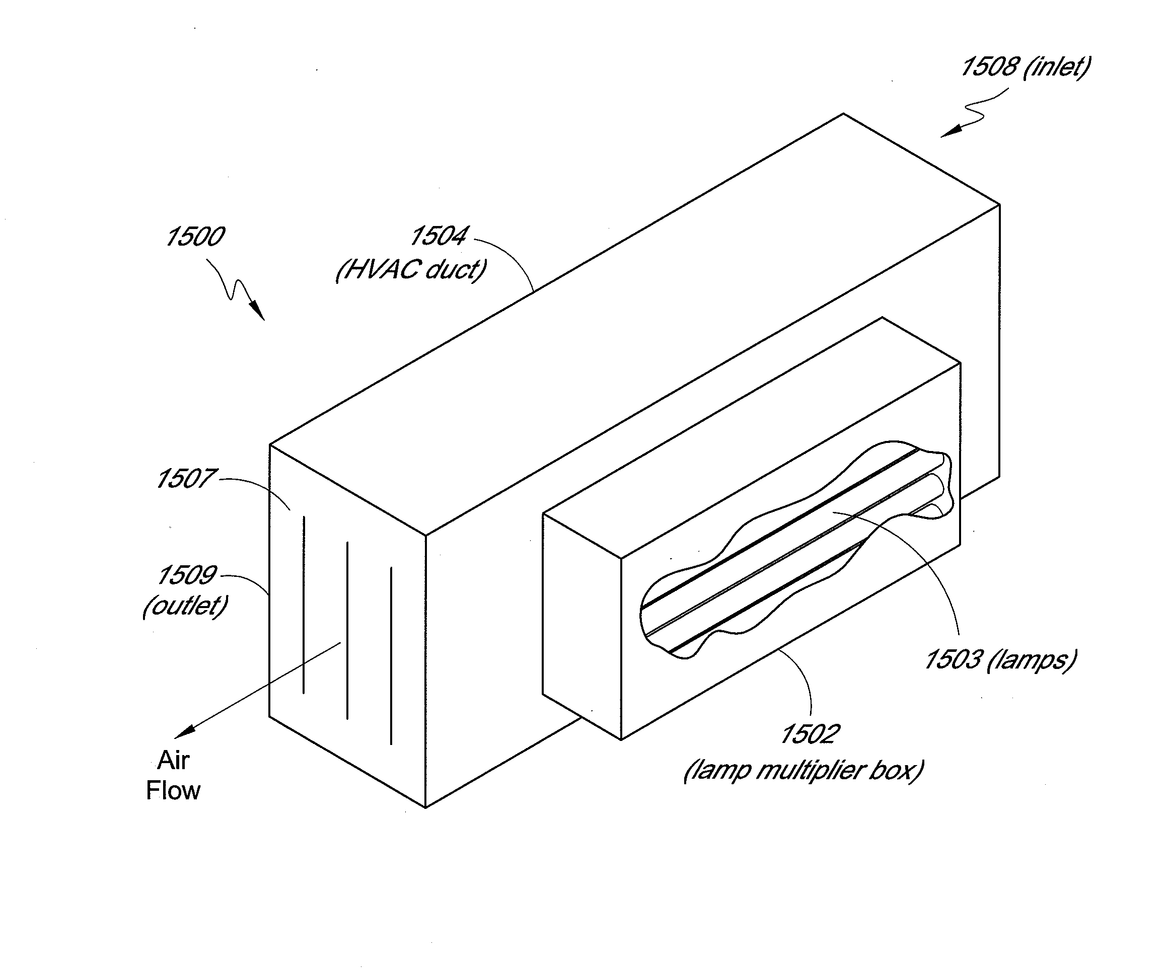
Single Germicidal Lamp in Lamp Multiplier Box

[0128]

HVAC Duct Dimensions.Boxlength80 inchesBoxwidth20 inchesBoxheight40 inchesPercent Open Ends14%Lamp Multiplier Box DimensionsBoxlength40 inchesBoxwidth 3 inchesBoxheight40 inchesWindow Dimensions40 inches × 40 inchesLamp length40 inchesLamp Diameter1.3 inches Reflectivity0.99Absorption of lamps per pass 4%UV output64 watts, CW

[0129]For a flow rate of about 3500 cubic feet per minute, this would result in a kill of Bacillus subtilis to about 1.15 logs. The power to the lamp would be about 340 watts.


PUM


Abstract

An ultraviolet flux multiplying air sterilization chamber comprises inner surfaces having a diffuse reflective behavior. The sterilization chamber includes an inlet aperture and an outlet aperture for air to flow through said chamber and a light source emitting an ultraviolet light. Due to the reflectivity of the inner surfaces of the chamber, a flux of the ultraviolet light is multiplied by reflecting multiple times from the inner surfaces of the chamber. The inlet and outlet apertures are advantageously configured to reduce the amount of light that escapes from the chamber and increase the amount of photons available in the chamber. In an exemplary embodiment, perforated end panels having diffuse, reflective interior surfaces may be provided over at least a portion of the inlet and outlet apertures.

Description

RELATED APPLICATION[0001]This application is a continuation-in-part of U.S. application Ser. No. 10 / 724,017, filed Nov. 26, 2003, now published as U.S. Publication No. 2004 / 0166018 A1, which claims the benefit of U.S. Provisional Application No. 60 / 429,880, filed Nov. 27, 2002, U.S. Provisional Application No. 60 / 471,485, filed May 15, 2003, U.S. Provisional Application No. 60 / 486,849, filed Jul. 10, 2003, Provisional Application No. 60 / 495,500, filed Aug. 14, 2003 and Provisional Application No. 60 / 496,195, filed Aug. 18, 2003, the disclosures of each of which are hereby incorporated by reference.GOVERNMENT RIGHTS[0002]The invention was made with government support and the government has certain rights in the invention.BACKGROUND OF THE INVENTION[0003]1. Field of the Invention[0004]This invention relates to a sterilization system that may be used for sterilizing air in HVAC systems and for other applications requiring high flux of UV light.[0005]2. Description of the Related Art[00...

Claims


Application Information

Patent Timeline
IPC IPC(8): A61L9/20
CPCA61L9/205A61L9/20A61L2209/16F24F8/22
Inventor CLARK, REGINALD W.EASTLUND, BERNARD J.INGRAM, MICHAEL W.STUMPF, JOSEPH C.
Owner NOVATRON
Why Eureka
Try Eureka