
Method and apparatus for commissioning power plants

a technology for power plants and equipment, applied in the direction of vortex flow apparatus, centrifugal force sediment separation, drying solid materials, etc., can solve the problems of clogging narrow steam passages, affecting the stability and rotation of stationary and rotating components of steam turbines, and affecting the time required to complete a project. , to achieve the effect of reducing fuel and water consumption and significantly reducing the time required to complete a proj

Active Publication Date: 2008-10-02
BEST ENERGY SERVICES INC
View PDF9 Cites 50 Cited by
  • Summary
  • Abstract
  • Description
  • Claims
  • Application Information

AI Technical Summary

Benefits of technology

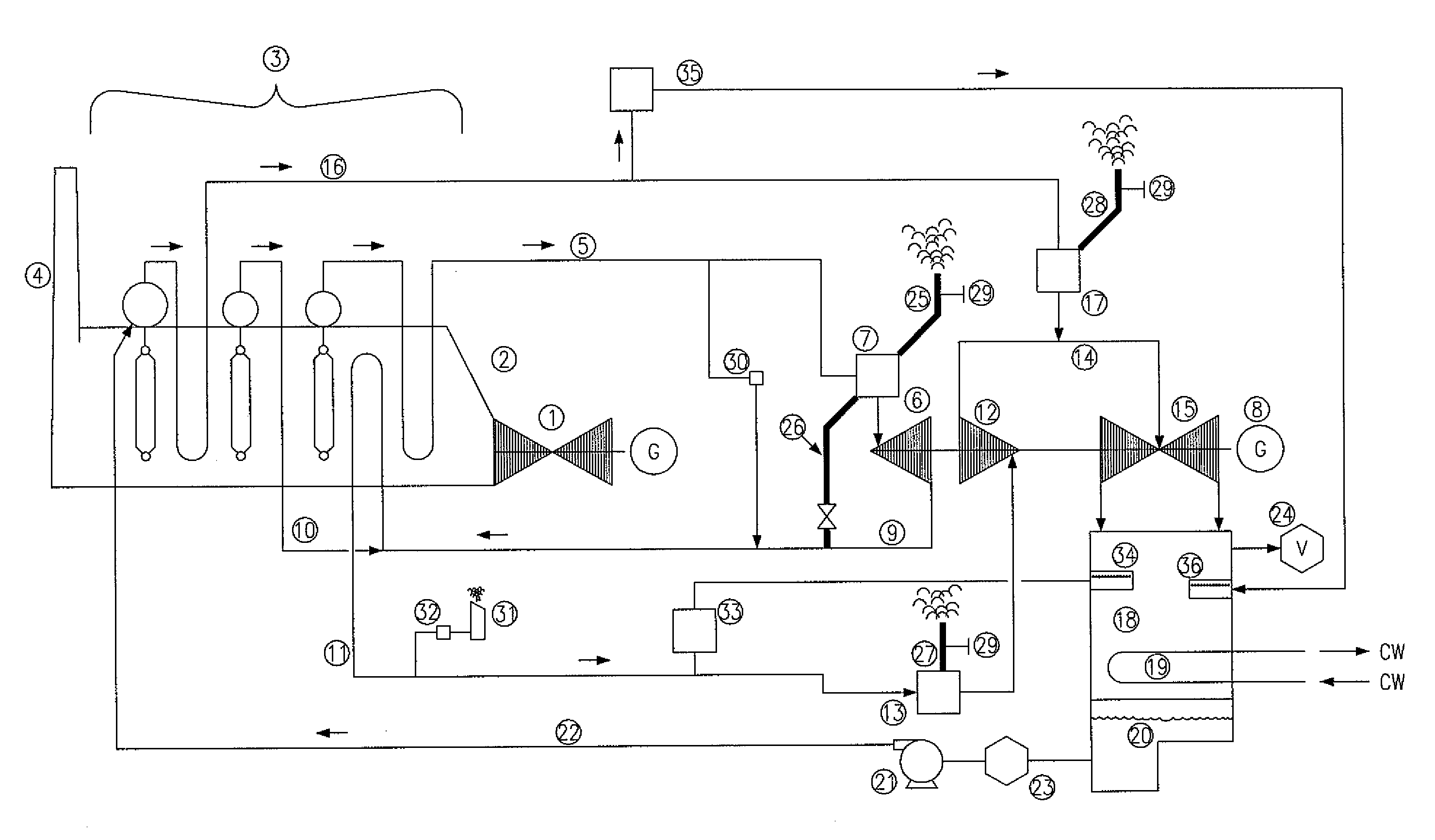
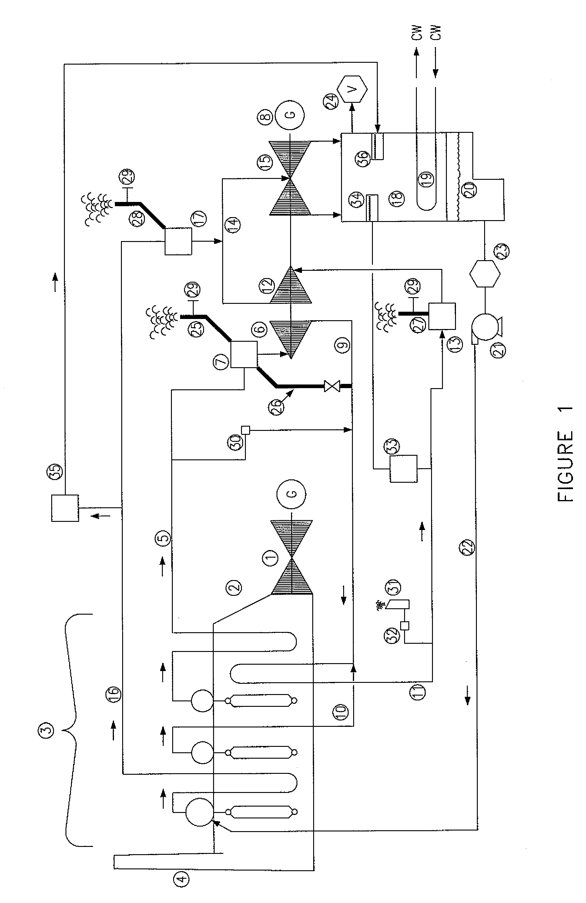
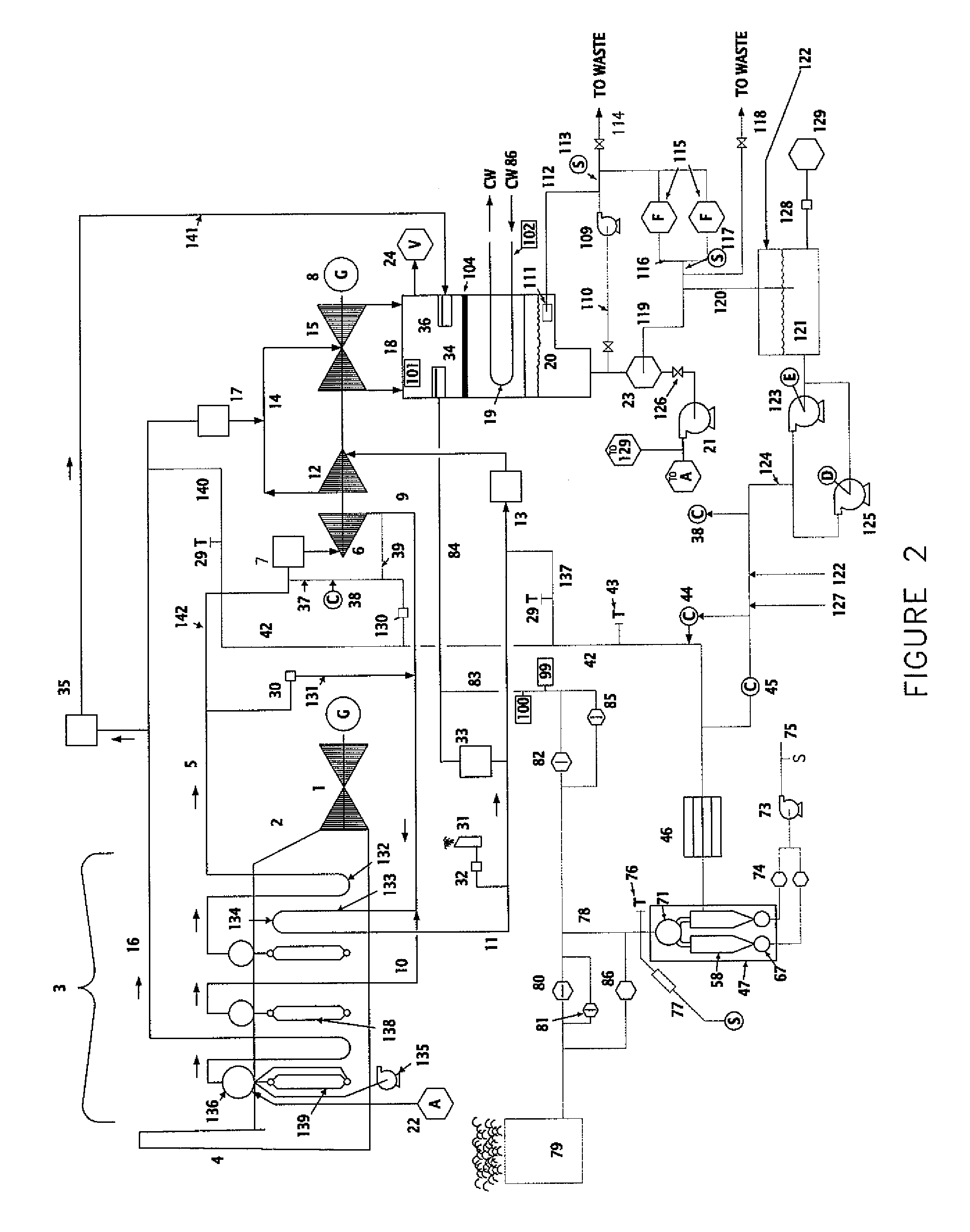
[0027]It is therefore an object of the present invention to provide an improved method for the cleaning of steam generation equipment and piping that supply both steam and / or gas turbines with a process that is integrated into the normal commissioning sequence of a new or refurbished steam generation facility. In this manner, the normal commissioning activities of the fuel supply, combustion and combustion gas exhaust systems as well as plant auxiliary systems may be tuned in parallel to the integrated cleaning activity. It is a further object of the present invention to reduce fuel and water consumption required for cleaning and commissioning. It is a further object of the invention to integrate of the decontamination and other commissioning activities so that, the time required to complete a project is significantly reduced.

Problems solved by technology

Particulate debris may plug start-up screens installed at the inlet control valves of the turbines or clog narrow steam passages.
Particulate debris may cause erosion or impact damage to both stationary and rotating components of the steam turbines.
Particulate debris may also plug or damage the internal surfaces of steam valves used to control the flow of steam.
The presence of anions in the steam will lead to the potential of stress cracking of steam turbine components.
Chlorides, organic anions and sulfates in the steam pose a particular danger for the onset of stress cracking.
The presence of sodium in the steam risks the deposition of alkalis and / or other salts.
Sodium chloride and sodium hydrogen sulfate also constitute a risk of stress corrosion cracking of turbine components.
While all of the above prior art methods may be successful in the removal of particulate contamination from the steam generator and pipe delivering steam to the steam turbine, the above prior art methods do not integrate the cleaning practices into other commissioning activities of the plant.
They do not integrate the removal of particulate contamination with the removal of other types of steam contamination such as silica, cation conductivity and salts.
Further the prior art cleaning methods typically limit the scope of the particulate debris cleaning effort to the steam generator, its associated piping and the steam piping.
Little if any effort is made to remove particulate and other contamination found in the condenser.
The chemical cleaning processes also generate large volumes of waste solution and waste flush water.
Prior art methods make little effort to optimize conditions that will increase the rate of silica, elements that contribute to cation conductivity and other salt contaminants.
The operation of a plant in steam bypass mode to the condenser is not optimized for the removal of silica and other contaminating salts in the steam.
Cooling of the bypass steam will result in the precipitation of silica dissolved in the steam.
In the prior art, the clean-up of the steam condensate to remove silica and other non-particulate contamination during turbine bypass operation is out of the scope of the existing steam system cleaning practices used to remove particulate contamination.
Corrosion following chemical cleaning, hydro-milling or other forms of mechanical cleaning may result in the formation of new particulate and salt contamination in the systems previously cleaned.
Use of corrosion inhibitors or other agents to preserve the cleaned surfaces may only exacerbate to amount of salts and organic compounds that will contaminate the steam during initial operation of the steam generator in bypass mode to the condenser.
The prior art practices of “discontinuous high pressure steamblow” and the “low pressure continuous steamblow” exhaust all steam from the steam cycle during the cleaning process, these methods require large volumes of high quality water, may take weeks to complete, and can result in environmental issues such as noise, related to the discharge of large volumes of steam.
In addition, these methods do not generate conditions highly favorable to the removal of silica, elements that result in elevated cation conductivity or other non-particulate steam contamination.
These methods also do not involve the condenser and therefore do nothing to address contamination that might originate from the extensive amount of contaminated metal surface area in the condenser.
These practices also require operation of the steam generator for an extended period of time with little possibility for other normal commissioning activities to be performed.
The fuel consumed during such steamblow operations represents a significant expense.
Extended operation of gas turbines of combined cycle power plants before tuning of the burners to minimize emissions during prior art methods also results in significant exhaust emissions.
In addition to the above, the prior art practices make only limited provisions for the assured protection of the condenser during the discharge of steam to the condenser.
Specifically, none of the prior art practices make adequate provisions to prevent the continued discharge of steam to the condenser should the condenser lose coolant flow or should attemperation water used to cool the steam being discharged to the condenser be interrupted.
Prior art practices that rely on operation of the steam system in bypass mode through the bypass valve do not provide an assured means of protecting plant bypass valves from contamination or conditions that may cause the bypass valve to not close fully when plant conditions would require such closure to protect the condenser from damage.
These same prior art methods make no provision to insure that the conditions generated by operation of the steam generation system in the bypass mode will optimize conditions for removal of either solid particle or other types of steam contamination due to the high pressure drop normally associated with typical bypass valves and the high back pressure of typical steam distribution sparge tubes in the condensers.
Although some prior art provides for the installation of sacrificial tubes in the top layer of the condenser tube bank, none of the prior art cleaning methods provide for an assured means of shielding condenser tubes from high velocity particles or moisture droplets discharged into the condenser at high velocities.
Most prior art steam system cleaning methods do not provide for the comprehensive treatment of the steam condensate generated in the condenser during bypass mode operation.
As a result, particulate contamination found in this condensate will result in the plugging of condensate and boiler feedwater pump strainers.
Use of ion exchange beds to remove salt ions is expensive and is rarely applied.
Further, the prior art methods do not provide a means of cleaning the steam exhausted from the steam generator and steam piping to remove contamination prior to the admission of the steam to the condenser.
Contamination transported by the initial steam discharged to the condenser will foul the condenser and may result in mechanical damage to the condenser due to the high velocity impingement of particulate contamination and entrained condensate droplets on the thin wall condenser tubing.
Although some prior art methods provide for the installation of a metal target plate into the bypass steam circuit to the condenser to monitor the presence of particulate contamination, none of the prior art methods make provision for the diversion of contaminated steam away from the condenser when particulate contamination is indicated by such targets.
In addition, prior art methods have not been practiced to generate physical and chemical conditions in the steam path that will insure the formation of a passive coating on the metal surfaces consistent with that formed by long term operation of the steam system at normal operating conditions.

Method used


Image

  • Method and apparatus for commissioning power plants
  • Method and apparatus for commissioning power plants
  • Method and apparatus for commissioning power plants

Examples


Embodiment Construction

[0130]The benefits of the present invention are based on the findings that considerable savings of time, fuel and water are realized by application of the enhanced method described by this current invention. In the preferred embodiment of the present invention both particulate and non-particulate contaminations are simultaneously removed from the steam cycle of a steam turbine plant at steam flow and temperature conditions significantly greater than the operational conditions used to complete removal of such contaminations from the steam cycle by means of the prior known art. In the prior art, the steamblow methods have been solely focused on the removal of only the particulate contamination. Unlike the present invention, the operational conditions during the steamblow were not manipulated to provide for the enhance removal of non-particulate contamination simultaneous to the operation of the unit to solely address removal of particulate contamination.

[0131]The present invention pro...


PUM

PropertyMeasurementUnit
Fractionaaaaaaaaaa
Velocityaaaaaaaaaa
Temperatureaaaaaaaaaa

Abstract

An apparatus and method for commissioning steam turbine generator power plants to advance the cleanliness of the complete steam cycle by the conditioned discharge of steam to the plant surface condenser.

Description

[0001]This application claims the priority date of Provisional Application Ser. No. 60 / 908,277, entitled METHOD AND APPARATUS FOR COMMISSIONING POWER PLANTS, filed on Mar. 27, 2007, which this application incorporates by reference in its entirety.FIELD AND BACKGROUND OF THE INVENTION[0002]The present invention relates to the commissioning of new and refurbished steam generation plant equipment and piping. More particularly, the present invention relates to the cleaning and conditioning of metal surfaces in the steam and water circuits associated with steam turbine generators and similar equipment at the same time that other essential commissioning activities are being performed.[0003]Steam turbines convert thermal energy from pressurized steam into mechanical energy. This mechanical energy is commonly used to drive electric generators or gas compressors. In combined cycle power plants, the exhaust heat of a gas turbine is used to generate steam that is then used to power a steam tur...

Claims


Application Information

Patent Timeline
IPC IPC(8): B08B3/00C23G1/00B04C3/06B08B9/027
CPCF22B37/486F22B37/52F16L57/06F26B5/04B08B3/02Y10T137/4245Y10T137/7043B08B2230/01
Inventor BLOCH, CHRISTOPHER J.
Owner BEST ENERGY SERVICES INC
Learn More