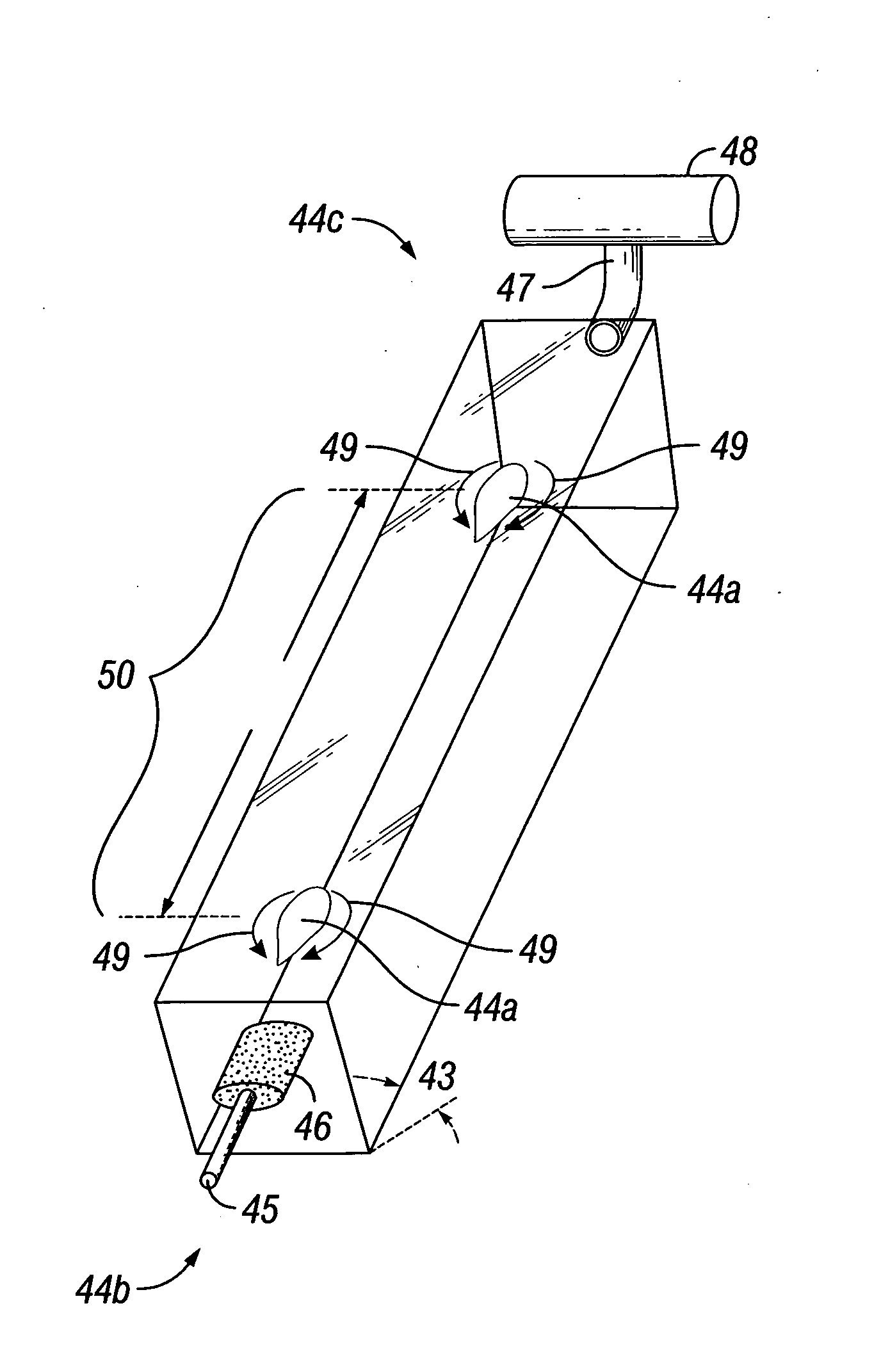
[0014]In many examples of the invention, the liquid contents of each chamber are still or very slow moving. Highly effective mixing will be achieved in some examples with low overall pressure and in the absence of turbulent bulk liquid flow by injecting a large bubble into the lower end of a chamber, and allowing the bubble to rise through a chamber. In further examples, large bubbles generate turbulent flow around their perimeters and displace the adjacent liquid, which mixes the liquid and the photo-microorganisms contained therein, as the large bubbles rise to the top of a chamber. In at least some examples, the large bubbles are characterized by a non-convex surface, typically in a trailing, bottom edge. The mixing induced by the generation of sufficiently large bubbles obviates the need to create
high pressure to induce
liquid circulation within each chamber. This in turn means that the chambers of this example can be made of lighter, more easily folded and transported, flexible material.
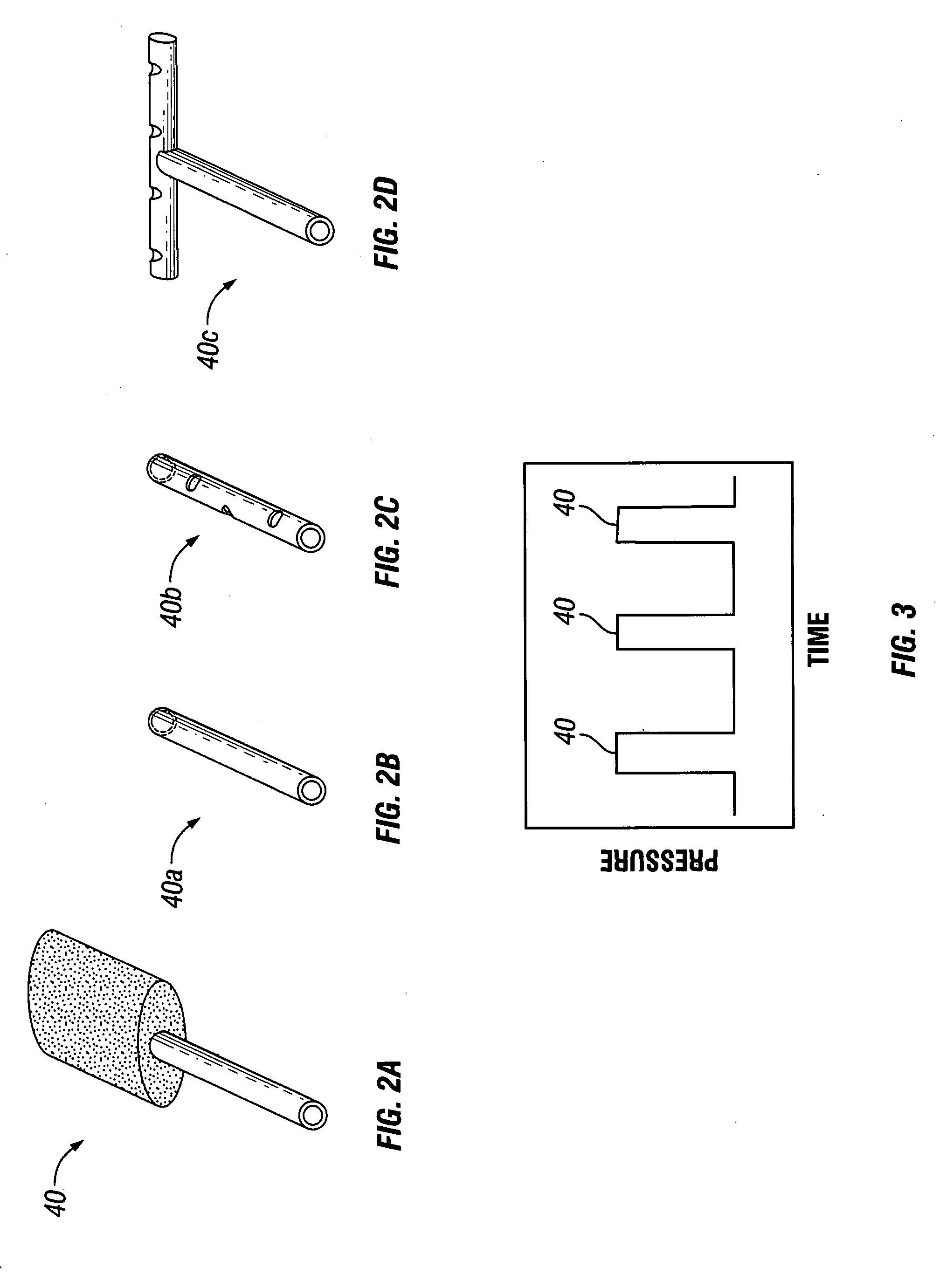
[0015]In one example, the large bubble generator consists of essentially the
gas supply line and optionally a sparger. Pulsing the
gas supply—pumping through large volumes of gas over a short period of time—will generate bubbles sufficiently sized to induce mixing in some examples. In other examples, a gas trap—in one configuration a flexible, hinged flap—will be used to generate sufficiently sized bubbles to generate the fluid flow required for mixing. In another example, a submerged
gas chamber with a reverse
siphon will be used to generate large bubbles. The latter two methods of generating a bubble within the chamber will be combined with a sparger in some examples. In some such embodiments, very small bubbles will be generated below or within the flexible flap or submerged
gas chamber. This will enhance gas
mass transfer (for instance
carbon dioxide dissolution) into the liquid.
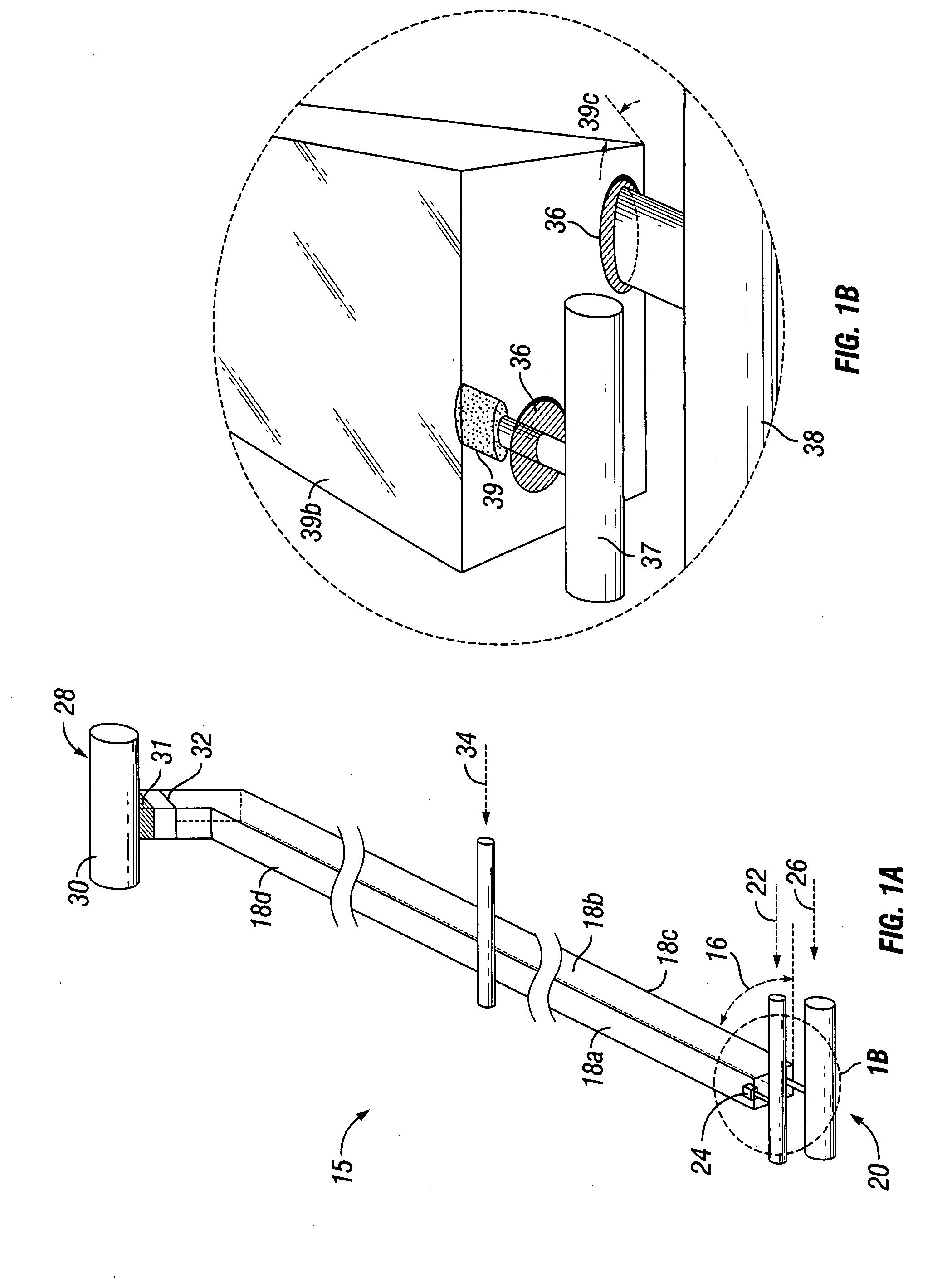
[0018]By inclusion of one or more of the features described in this document, a
system will be configured and put in working order at little material or labor cost (for example, by excavating an appropriately angled earthen
berm, unfurling and positioning the integrated unit comprising the photo-bioreactor on the inclined plane of the
berm with the gas vent line positioned to be elevated with respect to the
gas supply line, connecting the preinstalled gas supply line that is part of the integrated photo-bioreactor to a source of
carbon dioxide or other gas that can be used to support
algae or other photo-microorganism growth, and connecting the integrated liquid fill line and / or integrated liquid fill / drain line to a supply of
liquid medium, such as water and nutrients, needed to support microorganism growth) and connecting the liquid drain line and / or integrated liquid fill / drain line to a liquid drain. In some examples, the source of liquid and the liquid drain will be the same. Further advantages include easy and inexpensive preparation for
relocation by, for example, disconnecting the unit's gas supply line and liquid fill and / or liquid fill / drain line from their respective sources, disconnecting the liquid drain and / or liquid fill / drain line from their respective liquid drains and rolling up the integrated unit, inclusive of the preconnected gas supply line, liquid fill line, liquid drain line, and / or liquid fill / drain line and gas vent or disengager line, for storage and transportation by using a long rod as a spool.
[0020]The above examples enjoy lower manufacturing costs over other closed photo-bioreactor systems. This is due in part to the fact that many examples can be constructed using low cost materials and techniques that allow photo-bioreactors to be made in high volumes but at low cost. The flexible
plastic film (for example, 0.1 to 200 mil thick
polyvinyl chloride,
polyolefin,
polyethylene terephthalate,
polyimide,
polyurethane or similar plastics) that comprises the walls of the individual chambers in some examples, the material connecting the chambers and the necessary gas and water lines are much less costly than rigid plastics, metals or glass. The connections among the various components of the device—at the points of connection between (i) the walls of the chambers, (ii) the flexible material connecting individual chambers along their lengths and the chambers themselves and (iii) between the integrated gas and water lines and the connections thereto on the chambers—may be joined using low cost joining methods such as
plastic welding or adhesives.
[0021]In at least one example, the material comprising the integrated unit of the invention will be strengthened against punctures or
tears with fibrous reinforcement during the manufacturing process. Fibrous geo-
textile will be incorporated or embedded into the material of a photo-bioreactor. Alternatively, the fibrous
geotextile will be laminated or glued to the outside of the photo-bioreactor. Including
geotextile flaps that are flexibly connected, and extend beyond, the outside edges of the photo-bioreactor helps secure the photo-bioreactor to the angled earthen berm, or other angled site, and avoids the need, in the case of an earthen berm, to employ other
erosion control methods on surrounding ground areas when installed.


