

Polymer, polymer electrolyte membrane for polymer electrolyte fuel cell, and membrane/electrode assembly
- Summary
- Abstract
- Description
- Claims
- Application Information
AI Technical Summary
Benefits of technology
Problems solved by technology
Method used
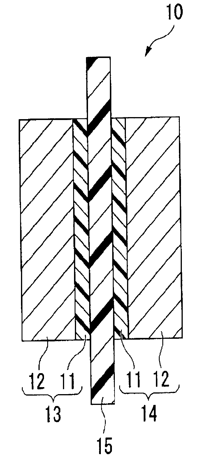
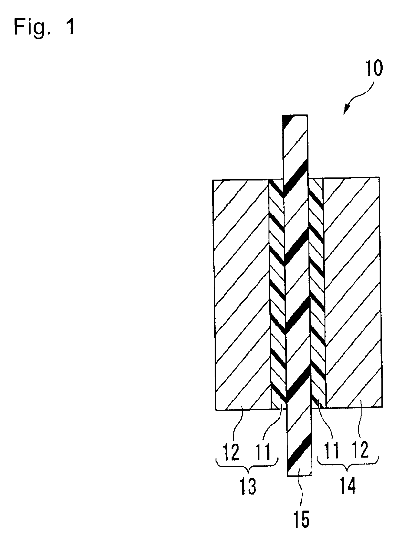
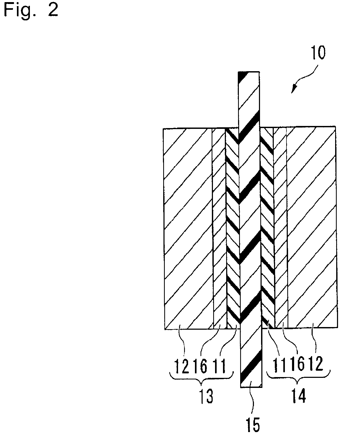
Image

Examples
example 1
[0201]Compound (m12) was prepared by the following synthetic route:
(i) Preparation of compound (a2):
[0202]Compound (a2) was prepared in the same manner as in the method as disclosed in Example 2 of JP-A-57-176973.
(ii) Preparation of compound (c2):
[0203]To a 300 cm3 four-necked round bottom flask equipped with a Dimroth condenser, a thermometer, a dropping funnel and a glass rod with an agitating blade, 1.6 g of potassium fluoride (tradename: Chloro-Catch F, manufactured by MORITA CHEMICAL INDUSTRIES CO., LTD.) and 15.9 g of dimethoxyethane were put in a nitrogen atmosphere. Then, the round bottom flask was cooled in an ice bath, and 49.1 g of compound (b11) was added dropwise from the dropping funnel over a period of 32 minutes at an internal temperature of at most 10° C. After completion of the dropwise addition, 82.0 g of compound (a2) was added dropwise from the dropping funnel over a period of 15 minutes. Substantially no increase in the internal temperature was observed. After ...
example 2
Preparation of Polymer F1
[0211]The interior of an autoclave (internal capacity: 2,575 cm3, made of stainless steel) was replaced with nitrogen, followed by sufficient deaeration. Under reduced pressure, 1,143.7 g of compound (m12), 205.2 g of compound (m21), 220.3 g of compound (2-1) as a solvent and 314.9 mg of compound (3-1) as a radical initiator were charged, and the autoclave was deaerated to the vapor pressure:
CClF2CF2CHClF (2-1),
(CH3)2C(CN)N═NC(CH3)2(CN) (3-1).
[0212]The internal temperature was raised to 65° C., tetrafluoroethylene (hereinafter referred to as TFE) was introduced to the autoclave, and the pressure was adjusted at 1.11 MPaG (gauge pressure). Polymerization was carried out for 6.0 hours while the temperature and the pressure were maintained constant. Then, the autoclave was cooled to terminate the polymerization, and the gas in the system was purged.
[0213]The reaction liquid was diluted with compound (2-1), and compound (2-2) was added to coagulate the polymer...
example 3
Preparation of Polymer F2
[0215]Polymer F2 which is a copolymer of TFE, compound (m12) and compound (m21) was obtained in the same manner as in Example 2 except that the conditions were changed as identified in Table 1 and that methanol was charged together with the monomers, the solvent and the radical initiator. The yield, EW, the ratio of repeating units constituting the polymer and the TQ value are shown in Table 1.
TABLE 1Ex. 2Ex. 3Obtained precursor polymerF1F2Autoclave (cm3)25751006Compound (m12) (g)1143.7334.5Compound (m21) (g)205.2239.4Compound (2-1) (g)220.3103.2Type of radical initiator(3-1)(3-1)Radical initiator (mg)314.9542.6Methanol (mg)020.4Polymerization temperature (° C.)6565Pressure (MPaG)1.111.2Polymerization time (hrs)6.06.5Yield (g)184.585.0EW (g / equivalent)641741Units (TFE) (mol %)8585.2Units (M12) (mol %)127.4Units (M21) (mol %)37.4U2 / (U1 + U2) (molar ratio)0.20.5TQ (° C.)253244
PUM
| Property | Measurement | Unit |
|---|---|---|
| Shrinkage | aaaaa | aaaaa |
| Electrical resistance | aaaaa | aaaaa |
| Equivalent weight | aaaaa | aaaaa |
Abstract
Description
Claims
Application Information