Multi-layered ceramic tube for fuel containment barrier and other applications in nuclear and fossil power plants

a technology of fuel containment barrier and multi-layer ceramic tube, which is applied in the direction of nuclear elements, lighting and heating apparatus, greenhouse gas reduction, etc., can solve the problems of affecting the performance affecting etc., to achieve the effect of improving the efficiency of nuclear power plants, and reducing the number of nuclear reactors

Inactive Publication Date: 2009-02-05
GAMMA ENG CORP
View PDF4 Cites 82 Cited by
  • Summary
  • Abstract
  • Description
  • Claims
  • Application Information

AI Technical Summary

Problems solved by technology

Failure of the fuel cladding can lead to the subsequent release of heat, hydrogen, and ultimately, fission products, to the coolant.
For example, metal cladding is relatively soft, and tends to wear and fret when contacted by debris that sometimes enters a coolant system and contacts the fuel.
Such wear and fretting can sometimes lead to breach of the metal containment boundary, and subsequent release of fission products into the coolant.
This additional heat from the cladding can exacerbate the severity and duration of an accident, as occurred at Three Mile Island.
Many metals may also lose strength when exposed to the high temperatures that occur during accidents.
For example, during a design basis loss of coolant accident, temperatures in a civilian nuclear power plant can reach as high as 2200 F (1204 degrees Celsius), and these high temperatures cause metals such as zirconium-based alloys to lose most of their strength and to expand like a balloon as a result of internal fission gas pressure.
This expansion tends to block coolant flow during the emergency cooling phase of the accident.
Similarly, a loss of flow accident that leads to film boiling on the surface of the fuel element creates a short duration increase in metal surface temperature and unacceptable strength loss and potential failure of the fuel element.
Zirconium alloy cladding tends to oxidize and become embrittled after long exposure to coolant, and this leads to premature failure during typical reactivity insertion accidents, where the fuel pellet heats up faster than the cladding leading to internal mechanical loading and failure of the embrittled metal cladding.
These composites overcome some of the above-described deficiencies of metal cladding, but themselves have certain deficiencies limiting their use.
For example, alumina composites can lose their strength under neutron radiation, thus limiting their ability to withstand the mechanical and thermal forces imposed during accidents.
This porosity causes the composite to be permeable to fission gases, however, thus permitting unacceptable leakage of fission gas through the cladding to the coolant.
The proposed tube, however, had several deficiencies that interfered with its reliable performance in existing commercial water reactors, or for advanced high temperature reactors that use water, gas, or liquid metal coolants.
For example, the woven fiber tows in the composite layer contained large voids that may interfere with the mechanical strength, thermal conductivity, and resistance to water logging required in fuel element cladding materials.
As a result, the monolith was more likely to fail at lower internal pressure than it would if the composite layer were able to share the load before the monolith reached its failure stress.
Woven fabric duplex tubes do not provide reinforcement and therefore would not provide this load sharing characteristic.

Method used


Image

  • Multi-layered ceramic tube for fuel containment barrier and other applications in nuclear and fossil power plants
  • Multi-layered ceramic tube for fuel containment barrier and other applications in nuclear and fossil power plants
  • Multi-layered ceramic tube for fuel containment barrier and other applications in nuclear and fossil power plants

Examples


example 1

Strength Measurements of Silicon Carbide Ceramic

[0077]FIG. 8 is a summary of temperature versus strength data for various types of silicon carbide composites, similar to the composite layer of the present ceramic tubes, as compared to conventional zirconium alloy. Data is taken from the open literature. The abbreviations used in FIG. 8 are explained in the following table.

AbbreviationMeaningSourceSiC - cgSiC / SiC composite with cg-Nicalon fibersS. J. Zinkle and L L. Snead ofORNLSiC - hi-nicSiC / SiC composite with Hi-Nicalon fibersH. Ichikawa of Nipponwith PIP matrix and BN interphaseCarbonSiC - Type-sSiC / SiC composite with Hi-Nicalon type-SH. Ichikawa of Nipponfibers with PIP matrix and BN interphaseCarbonSiC - TyrannoSiC / SiC composite with Tyranno-SA fibersT. Nozawa and L. L. Sneadwith CVI matrix and PyC interphaseof ORNLZirc-4 BilloneFramatome low-tin Zircaloy-4M. C. Billone of ANLZirc-2Zircaloy-2E. Lahoda

[0078]As illustrated in FIG. 8, zircaloy loses virtually all of its strength a...

example 2

Fabrication of Ceramic Tubes

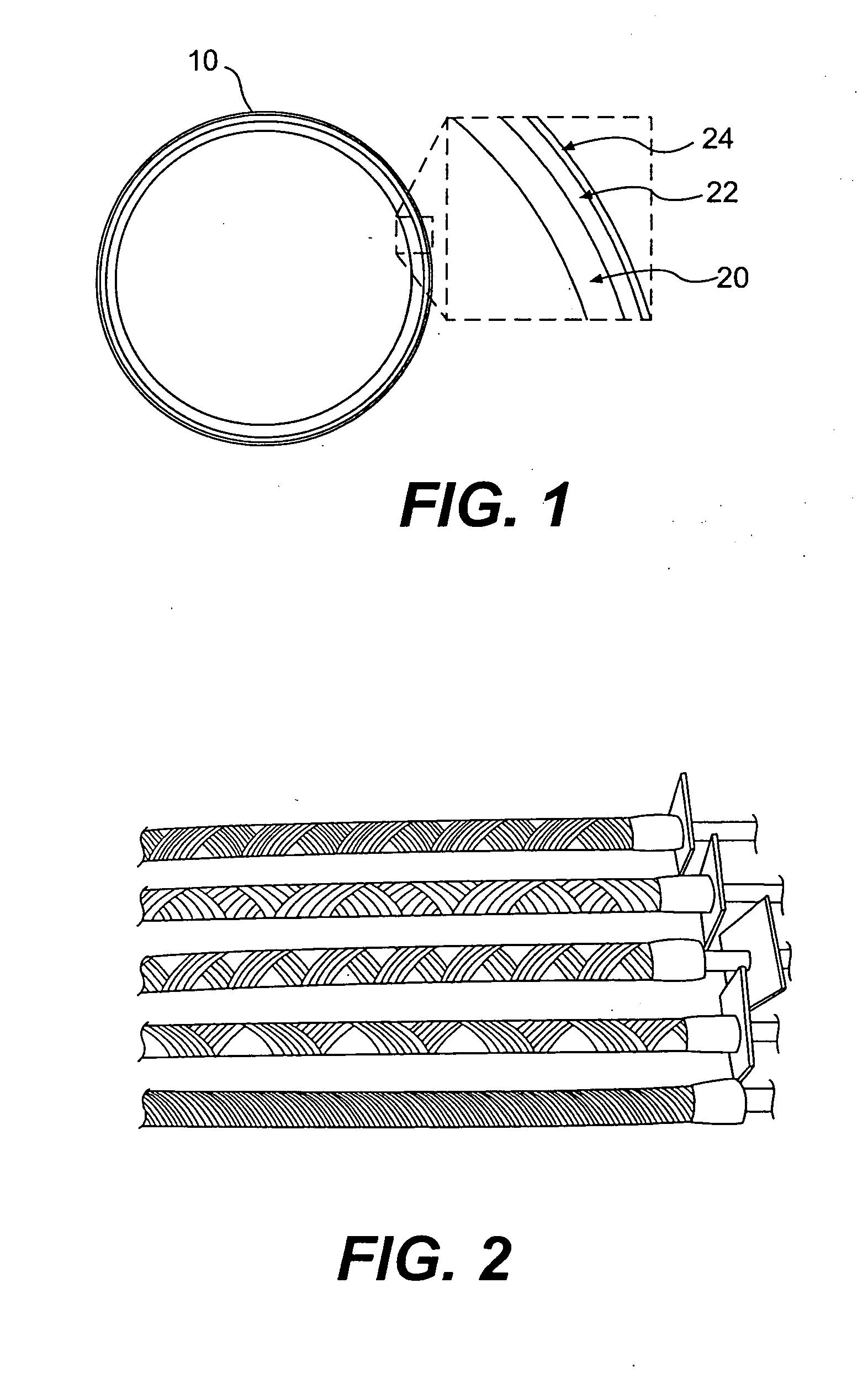
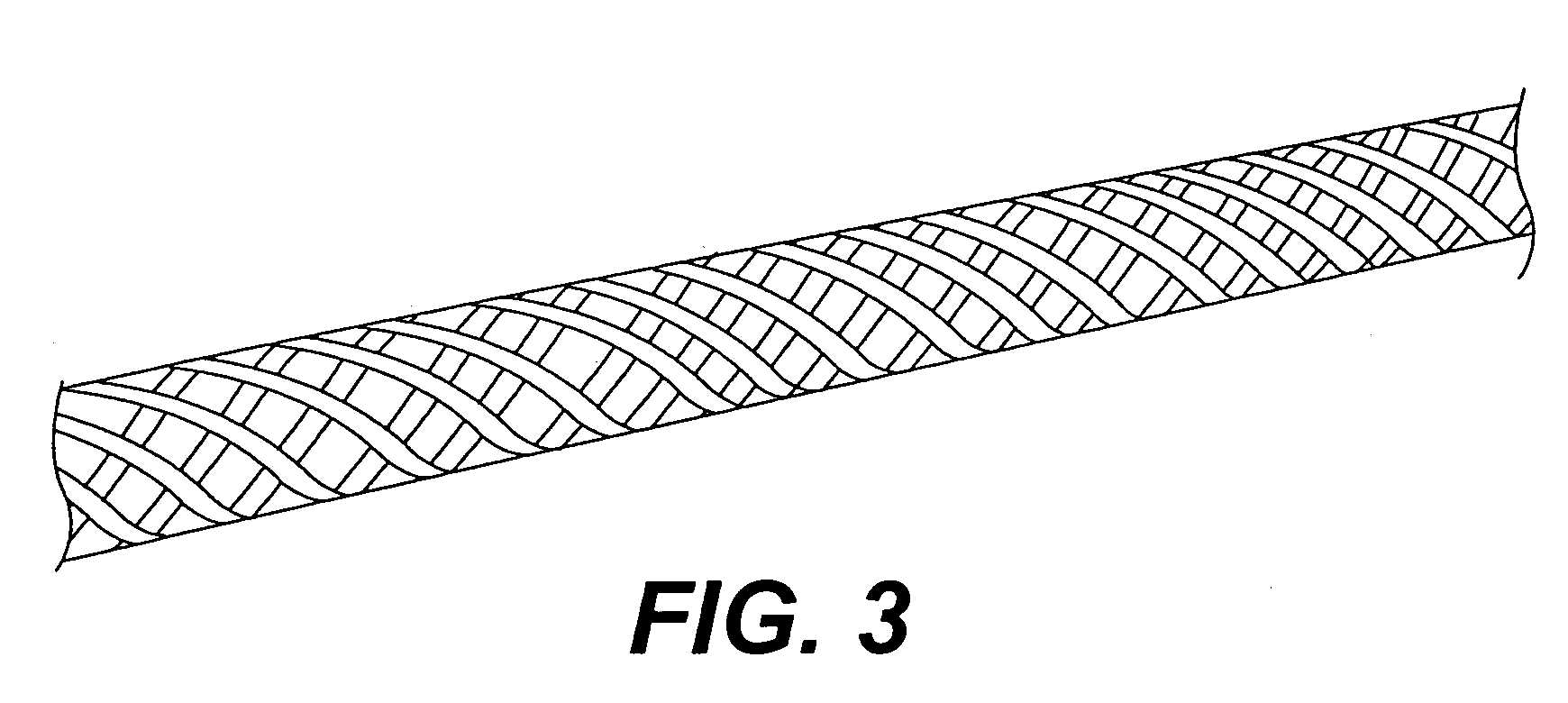
[0079]Exemplary two-layered ceramic tubes of the present invention were formed by the following process. First, Chemical Vapor Deposition (CVD) processes were used to form the inner monolith layer of high purity beta phase stoichiometric silicon carbide, according to techniques known in the art. Second, commercially available fiber tows, formed of 500 to 1600 high purity, beta phase, silicon carbide fibers of 8 to 14 micron diameter, were wound tightly on the inner monolith tube, in a variety of winding patterns and using a variety of winding angles, as shown in FIGS. 2 and 3, to make “pre-forms.”

[0080]These “pre-forms” were then coated with a thin pyrolytic carbon interface layer, and then impregnated with a SiC matrix, using an isothermal pulsed flow technique of chemical vapor infiltration, described as “Type V” in T. M. Besmann et al., “Vapor Phase Fabrication and Properties of Continuous Filament Ceramic Composites,” Science 253:1104-1109 (Sep. 6, 19...

example 3

Fabrication of Prior Art Tubes

[0082]FIG. 9B illustrates two silicon carbide tubes fabricated according to the method set forth in Feinroth et al. After formation of a relatively thick monolith layer (about 0.125 inches), the tubes were covered with silicon carbide. The left tube was covered with hoop-wound silicon carbide fibers, and the right tube was covered with woven or braided silicon carbide fibers. Further details are provided in H. Feinroth et al., “Progress in Developing an Impermeable, High Temperature Ceramic Composite for Advanced Reactor Clad Application,” American Nuclear Society Proceedings—ICAPP conference (June 2002). The pre-forms were impregnated with a SiC matrix, using the method described in Example 2.


PUM

PropertyMeasurementUnit
angleaaaaaaaaaa
thicknessaaaaaaaaaa
internal porosityaaaaaaaaaa

Abstract

A multi-layered ceramic tube having an inner layer of high purity beta phase stoichiometric silicon carbide, a central composite layer of continuous beta phase stoichiometric silicon carbide fibers, and an outer layer of fine-grained silicon carbide. The ceramic tube is particularly suited for use as cladding for a fuel rod used in a power plant or reactor. The ceramic tube has a desirable combination of high initial crack resistance, stiffness, ultimate strength, and impact and thermal shock resistance.

Description

CROSS-REFERENCE TO RELATED INVENTIONS[0001]This application claims the benefit under 35 U.S.C. Section 119(e) to U.S. Provisional Application Ser. No. 60 / 577,209, filed Jun. 7, 2004, which is herein incorporated by reference in its entirety.STATEMENT REGARDING FEDERALLY SPONSORED RESEARCH[0002]The technology described in this application was developed, in part, under a Small Business Innovative Research Grant from the US Department of Energy—Grant # DE-FG02-OER83194.BACKGROUND[0003]This invention relates to a device used to contain fissile fuel within nuclear power reactors. In many of today's nuclear reactors, the fuel is contained within sealed metal tubes, commonly called “fuel cladding”, which are generally made of an alloy of zirconium or a steel alloy. The fuel cladding is designed to assure that all radioactive gases and solid fission products are retained within the tube and are not released to the coolant during normal operation of the reactor or during conceivable accident...

Claims


Application Information

Patent Timeline
Patent Type & Authority Applications(United States)
IPC IPC(8): B29C53/58B05D7/22
CPCC04B35/806F28F21/04G21C3/07G21Y2002/104Y02E30/40G21Y2002/303G21Y2004/10G21Y2004/30G21Y2002/206Y02E30/30C04B35/62897C04B35/62873C04B35/80C04B35/565C04B2235/767C04B2235/365C04B2237/38C04B2237/365C04B2237/765C04B2235/5264C04B2235/5268C04B35/571C04B2235/614G21C3/00G21C3/06
Inventor FEINROTH, HERBERT
Owner GAMMA ENG CORP
Why Eureka
Try Eureka