Ultrasonic stirring of liquids in small volumes

a technology of ultrasonic stirring and liquids, applied in the field of ultrasonic stirring of liquids in small volumes, can solve the problems of difficult stirring and mixing in small volumes, ineffective application of conventional mixing strategies to microfluidic volumes, and tedious multi-step process of fabrication, etc., to achieve rapid and effective stirring of liquids

Inactive Publication Date: 2009-02-26
ARTANN LAB
View PDF8 Cites 25 Cited by
  • Summary
  • Abstract
  • Description
  • Claims
  • Application Information

AI Technical Summary

Benefits of technology

[0013]Accordingly, it is an object of the present invention to overcome these and other drawbacks of the prio

Problems solved by technology

Stirring and mixing in small volumes is, however, difficult.
Applying conventional mixing strategies to microfluidic volumes is generally ineffective.
Although performance of these devices is in many cases satisfactory, their fabrication is usually a tedious, multi-step process.
The lack of moving parts makes passive mixers free of additional friction and wear effects, but their intricate channel topologies are often hard to fabricate, and they are

Method used


Image

  • Ultrasonic stirring of liquids in small volumes
  • Ultrasonic stirring of liquids in small volumes
  • Ultrasonic stirring of liquids in small volumes

Examples


first embodiment

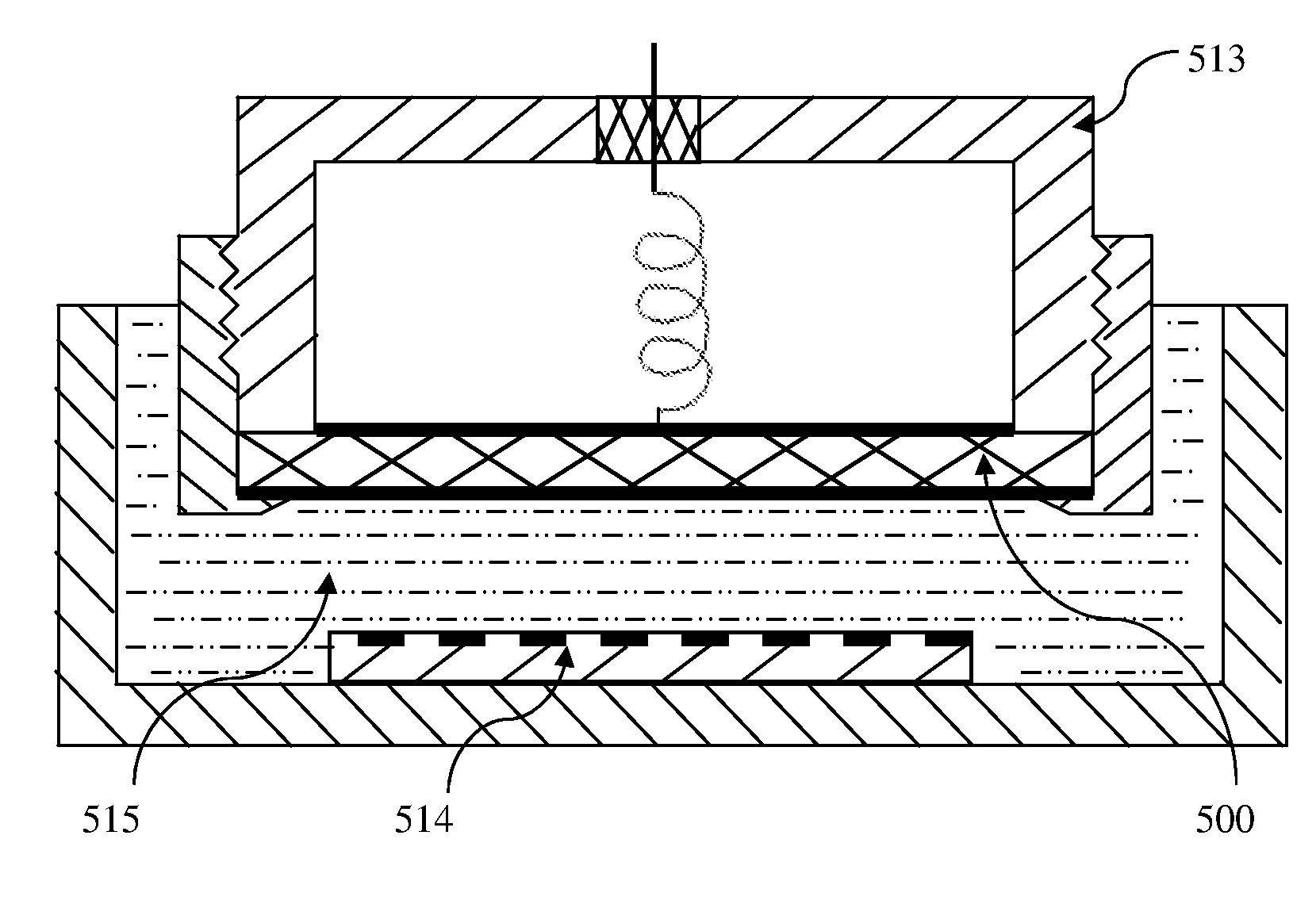
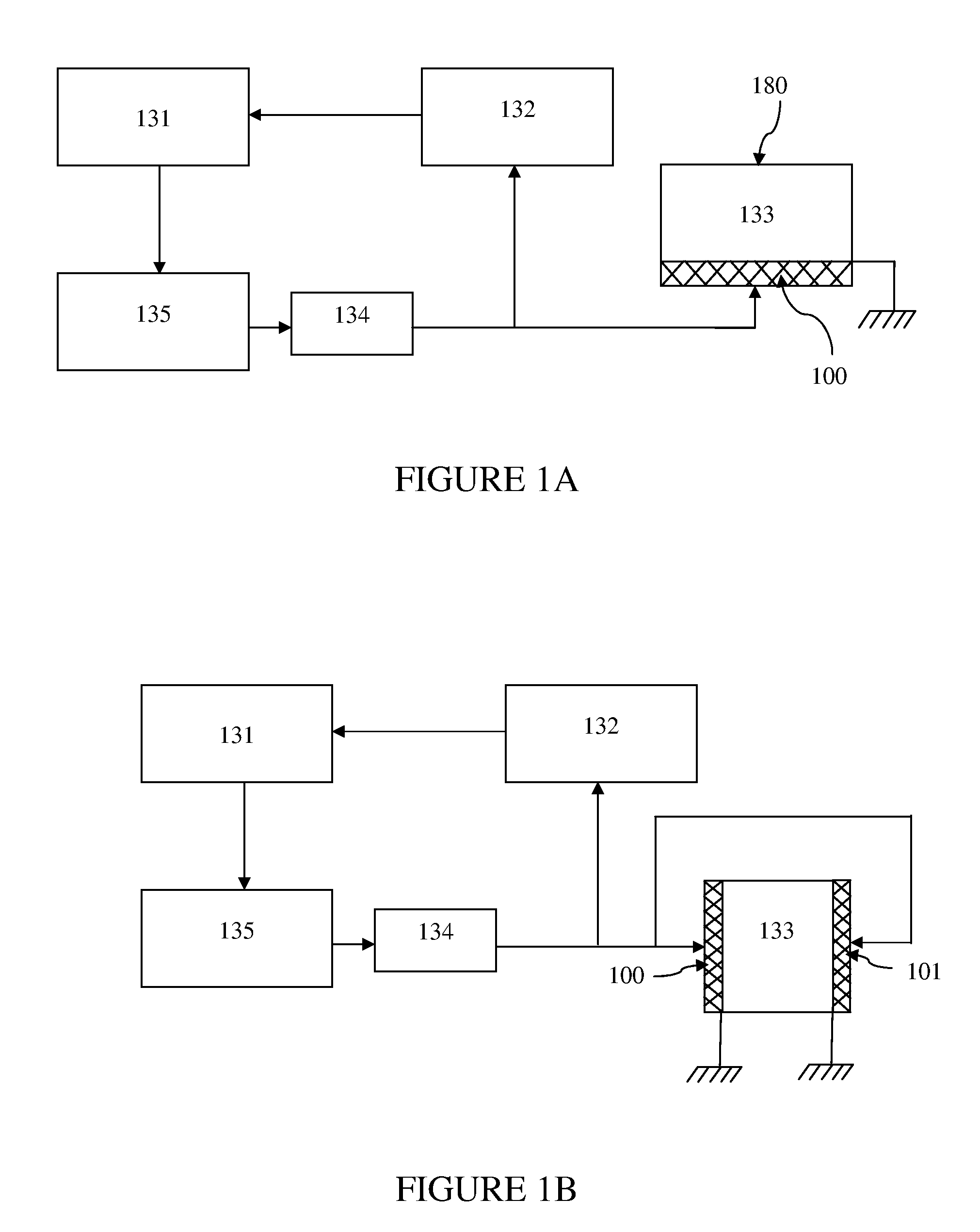
[0047]Referring to FIG. 1A, there is shown a block-diagram of the device according to the invention. The device includes a transducer 100 that generates ultrasonic standing waves at various harmonics in the liquid filling the resonator cell 133. The resonator cell 133 can be formed between the liquid-contacting surface of the transducer 100 and a plane-parallel acoustic reflector 180 located opposite the transducer 100 so that ultrasonic wave may travel back and forth forming standing waves at certain resonance frequencies of the liquid column above the transducer. The transducer 100 is typically a disc, plate or a film made of piezoceramics, piezopolymer, or other material that can generate acoustic waves under alternating current excitation. The resonator cell 133 could be also formed by a vessel of arbitrary internal shape as long as its walls provide effective reflection of acoustic waves, creating at certain frequencies the nodes of standing waves in the liquid filling the vess...

second embodiment

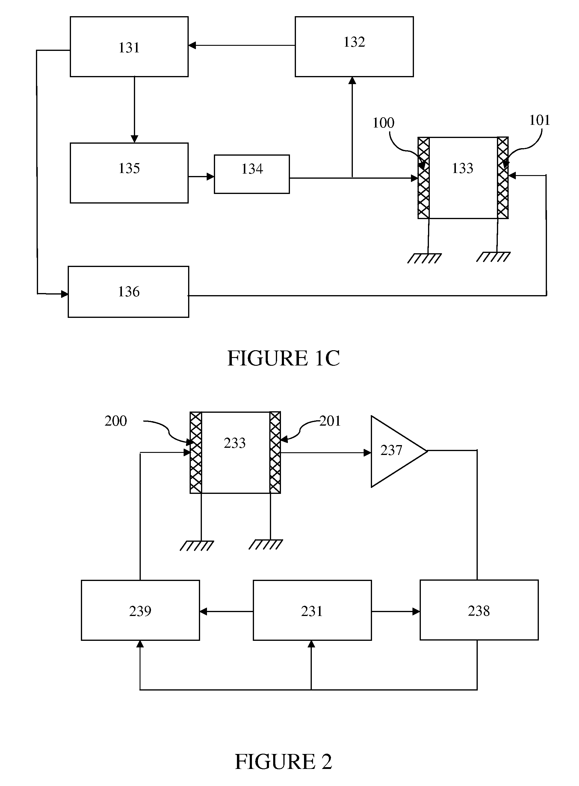
[0059]FIG. 2 shows a schematic block-diagram of the invention. In the device according to this embodiment of the invention, an ultrasonic resonator cell 233 is formed by two plane-parallel piezotransducers 200 and 201 and is connected to a simple oscillation and feedback control system, including a broadband amplifier 237, a phase-locked loop chip 238, a microprocessor 231 and a bandpass filter 239. The transducer 201 serves both as a reflector and a receiver of ultrasound. FIG. 3 shows frequency dependences of amplitude and phase of the signal at the receiving transducer 201 in a frequency band covering several resonance harmonics fn−1, fn, and fn+−1. The phase of the signal from the receiving transducer 201 is changed by 180° when the frequency is swept through a region corresponding to a resonance peak marked by bold lines on the frequency axis of the graph of FIG. 3. As seen in FIG. 3, the inflection point of the phase / frequency curve corresponds to the maximum of the resonance ...

third embodiment

[0062]FIG. 4 illustrates an implementation of the resonator cell according to the invention. This design is particularly useful to facilitate mixing of two or more liquids using magnetic microbeads in a flow-through device for microfluidic applications. In the illustrated arrangement, the two liquids being mixed are supplied from different inlets 310 and 320 leading into a resonator cell 333. Some magnetic microbeads 340 are also fed into the resonator cell 333 along with the mixing liquids. Magnetic microbeads, such as for example micron-scale particles, are used in a variety of biotechnology applications, most notably for cell sorting and assay separations [as described in Choi, J.-W., C. H. Ahn, S. Bhansali, and H. T. Henderson. A new magnetic bead-based, filterless bio-separator with planar electromagnet surfaces for integrated bio-detection systems. Sens. Actuators B Chem. 2000, 68:34-39]. Magnetic microbeads are commercially available from numerous commercial sources and are c...


PUM


Abstract

Ultrasound-assisted contactless stirring of liquids in a resonator cell by microparticles is achieved by repeated creating and destruction of nodal patterns associated with standing waves of various resonance frequencies causing continuous movements of microparticles inside the cell. Swept-frequency sonication methods include using constant or variable rate of frequency change as well as a stepwise change of frequency of the transducer within a predefined range. Other useful steps include initial detection of the set of resonance frequencies and periodic refreshing of that set. Control systems are described including means to automatically detect the resonance frequencies and maintain the operation of the transducer thereon. Advantageous designs of the apparatus are described for use in microstirring, mixing of liquids using magnetic microbeads, microbubbles, microtiter plates, microarray plates, etc.

Description

FIELD OF THE INVENTION[0001]The present invention relates to a method and apparatus for ultrasonic contactless stirring and mixing of small amounts of liquids. More specifically, the invention relates to the use of a swept-frequency mode of sonication to induce rapid motion of microparticles suspended in the liquid such that these microparticles cause efficient stirring of the liquid. The invention can be best utilized to facilitate various processes, which require mixing, agitation, and stirring of small volumes of liquids.BACKGROUND OF THE INVENTION[0002]Stirring and mixing liquids is a necessary part of many industrial, chemical and pharmaceutical technological processes. The majority of these industrial processes are carried out on macroscopic levels. It has only been in the recent years that mixing of small quantities of liquids has become technologically relevant in the context of microfluidics since mixing is often crucial to the effective functioning of devices manipulating ...

Claims


Application Information

Patent Timeline
IPC IPC(8): B01F11/02
CPCB01F11/0266B01F13/0059B01F11/0283B01F31/87B01F31/86B01F33/30
Inventor SARVAZYAN, ARMEN P.
Owner ARTANN LAB
Why Eureka
Try Eureka