Method for manufacturing conductive composite material

Inactive Publication Date: 2009-03-05
TOPNANOSIS
View PDF3 Cites 128 Cited by
  • Summary
  • Abstract
  • Description
  • Claims
  • Application Information

AI Technical Summary

Benefits of technology

[0014]A conductive fiber thin-film is fixed to a base layer by fixing a conductive fiber in a conductive fiber dispersion solution to the base layer and removing the remaining materials through the base layer. Accordingly, the conductive fiber thin-film is reduced in thickness, resulting in enhanced transparency. In addition, the conductive fiber thin-film is formed of the conductive fiber, resulting in enhanced conductivity.
[0015]In addition, since part of the conductive fiber thin-film is dispersed and inserted into part of the base layer,

Problems solved by technology

However, ITO is brittle such that it is mechanically unstable when folded or bent.
Furthermore, ITO tends to be deformed when thermally expanded.
However, since the conductive polymer absorbs visible light, an electrode coated with a thick conductive polymer has a very poor light transmissivity.
In addition, since most of the conductive polymers are insoluble, their thin-film processes are very complicated and their applicable process temperatures are very low.
That is, since the carbon nanotube 12a is dispersed in the binding agent 12b, a relatively large amount of carbon

Method used


Image

  • Method for manufacturing conductive composite material
  • Method for manufacturing conductive composite material
  • Method for manufacturing conductive composite material

Examples


embodiment 1

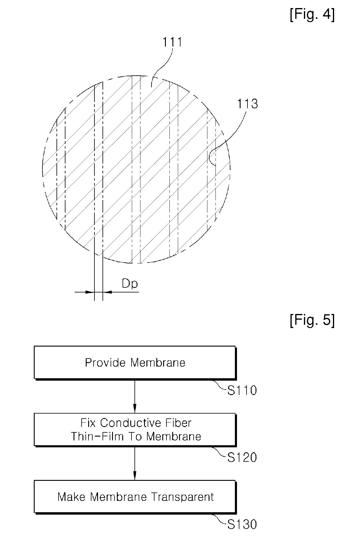
[0093]A carbon nanotube was used as the conductive fiber 130, and a polyethersulfone membrane with pores 113 each having a diameter of 0.2 mm was used.

[0094]The conductive fiber thin-film 130 was fixed to the membrane using the vacuum filter shown in FIG. 6. Referring to FIG. 6, 0.0015 wt % carbon nanotube aqueous dispersion solution 140 was prepared by adding 15 mg of a single-walled carbon nanotube 131 (mfg. by ILJIN Nanotech) to 11 of aqueous solution 141 in which 10 g of SDS as a surface active agent was dissolved, and applying 40 kHz ultrasonic waves of 45 W for 30 minutes.

[0095]Next, 80 ml of the carbon nanotube aqueous dispersion solution 140 from the container 150 was filtered by the large-sized vacuum filter 160 with a filtering area of 500 cm2.

[0096]In this case, the base layer 110 made of a polyethersulfone membrane with pores each having a diameter of 0.2 mm is provided in the large-sized vacuum filter 160. A solvent except the carbon nanotube was filtered through the po...

embodiment 2

[0102]The transparent conductive composite material 100 was prepared in the same method as that of Embodiment 1, except that a carbon nanotube / membrane composite material with a small amount of dimethylformamide (DMF) coated passed through a heating roller with a temperature of 80° C. to make the membrane film transparent.

[0103]The transparency, conductivity, uniformity of conductivity, and adhesion stability of the transparent film thus manufactured were examined in the same method as that of Embodiment 1. As a result, the transparent film was proved to have excellent transparency, conductivity, uniformity of conductivity, and adhesion stability, similarly to that of Embodiment 1.

embodiment 3

[0104]The transparent conductive composite material 100 was prepared in the same manner as that of Embodiment 1, except that during the process of making transplant the membrane having the carbon nanotube film formed thereon, an optically transparent polyethylene terephtalate film was stacked on a lower surface of a polymer film, and a carbon nanotube / membrane composite material with a small amount of dimethylformamide (DMF) coated passed through a heating roller with a temperature of 80° C. to make the membrane film transparent.

[0105]The transparency, conductivity, uniformity of conductivity, and adhesion stability of the conductive composite material thus manufactured were examined in the same method as that of Embodiment 1. As a result, the transparent film was proved to have excellent transparency, conductivity, uniformity of conductivity, and adhesion stability, similarly to that of Embodiment 1.


PUM

PropertyMeasurementUnit
Diameteraaaaaaaaaa
Temperatureaaaaaaaaaa
Pressureaaaaaaaaaa

Abstract

A conductive composite material is provided, including: a base layer; a conductive fiber thin-film made of conductive fiber and formed on the base layer; and a mixture layer in which part of the conductive fiber is inserted into part of the base layer.

Description

TECHNICAL FIELD[0001]The present invention relates to a conductive composite material, which is flexible and used in an electronic product such as a flat panel display, and a method for manufacturing the same.BACKGROUND ART[0002]Transparent conductive materials have been widely used in a thin-film transistor liquid crystal display (TFT-LCD), a plasma display panel (PDP), an organic light emitting diode (OLED), a touch panel, an electromagnetic-wave shield, an electrostatic-discharge shield, a heat reflector, a surface heater, a photo-electric converter, etc.[0003]Indium tin oxide (ITO) has been widely used as a transparent conductive material because of its good electrical characteristics and high light transmissivity. However, ITO is brittle such that it is mechanically unstable when folded or bent. Furthermore, ITO tends to be deformed when thermally expanded.[0004]As an electrode material, researches have recently been focused on conductive polymers, such as polyacetylene, polypy...

Claims


Application Information

Patent Timeline
IPC IPC(8): B32B37/02B05D5/12
CPCB32B27/12C09D5/24H01B1/24H01J2209/02H01J2211/225B32B27/285Y10T156/10B32B27/36B32B2262/106B32B2307/202B32B2307/412B32B2457/00B32B2457/20B32B27/286
Inventor OH, SANG-KEUNPARK, JUNE-KI
Owner TOPNANOSIS
Why Eureka
Try Eureka