
Recompressed exfoliated graphite articles

a graphite and composition technology, applied in the direction of non-metal conductors, conductors, synthetic resin layered products, etc., can solve the problems of significant impact on the performance, durability, cost, and cost of a fuel cell system, and achieve the effects of less anisotropy, enhanced isotropy, and easy molded or embossed

Inactive Publication Date: 2009-03-05
NANOTEK INSTR GRP LLC
View PDF33 Cites 23 Cited by
  • Summary
  • Abstract
  • Description
  • Claims
  • Application Information

AI Technical Summary

Benefits of technology

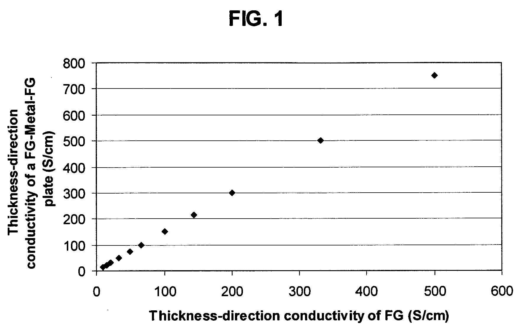
[0038]It may be noted that the US Department of Energy (DOE) target for composite bipolar plates includes a bulk electrical conductivity of 100 S / cm or an areal conductivity of 200 S / cm2, where the areal conductivity is essentially the ratio of the thickness-direction conductivity to the plate thickness. This implies that a thinner plate has a higher areal conductivity, given the same thickness-direction conductivity. One of the advantages of the presently invented recompressed graphite composition is the notion that this composition can be prepared in such a manner that the resulting composite plate can be as thin as 0.3 mm, in sharp contrast to the conventional graphite bipolar plates which typically have a thickness of 3-5 mm. This, when coupled with the fact that bipolar plates typically occupy nearly 90% of the total fuel cell stack thickness, implies that our technology enables the fuel cell stack size to be reduced dramatically. The resulting plates have electrical conductivities far exceeding the DOE target values, which was an original objective of the DOE-sponsored research and development work that resulted in the present invention.

Problems solved by technology

The bipolar plate is known to significantly impact the performance, durability, and cost of a fuel cell system.
The bipolar plate, which is typically machined from graphite, is one of the most costly components in a PEM fuel cell.
Such plates are expensive due to high machining costs.
The machining of channels into the graphite plate surfaces causes significant tool wear and requires significant processing times. Metals can be readily shaped into very thin plates, but long-term corrosion is a major concern.
It is often difficult and time-consuming to properly position and align the separator and stencil layers.
Die-cutting of stencil layers require a minimum layer thickness, which limits the extent to which fuel cell stack thickness can be reduced.
Such laminated fluid flow field assemblies tend to have higher manufacturing costs than integrated plates, due to the number of manufacturing steps associated with forming and consolidating the separate layers.
They are also prone to delamination due to poor interfacial adhesion and vastly different coefficients of thermal expansion between a stencil layer (typically a metal) and a separator layer.
Corrosion also presents a challenging issue for metal-based bipolar plates in a PEM fuel cell since they are used in an acidic environment.
Because most polymers have extremely low electronic conductivity, excessive conductive fillers have to be incorporated, resulting in an extremely high viscosity of the filled polymer melt or liquid resin and, hence, making it very difficult to process.
It is well-known that CVI is a very time-consuming and energy-intensive process and the resulting carbon / carbon composite, although exhibiting a high electrical conductivity, is very expensive.
Clearly, this is also a tedious process which is not amenable to mass production.
Although flexible graphite sheets are highly conductive (in a direction parallel to the sheet plane), they by themselves may not have sufficient stiffness and must be supported by a core layer or impregnated with a resin.
Prior art flexible graphite sheets fall short of this conductivity level.
By allowing ceramic or glass fibers to puncture through layers of exfoliated graphite also leave these layers vulnerable to gas permeation, thereby significantly reducing the hydrogen and oxygen permeation resistance of a bipolar plate and increasing the chance of dangerous mixing of hydrogen and oxygen inside a fuel cell stack.
However, it failed to teach, implicitly or explicitly, how a desired degree of isotropy could be maintained when the bi-axially, tri-axially, cylinder-radially, and isostatically compressed composite compacts (prior to curing or fusing to consolidate) were re-compressed or molded as a final operation to become a thin composite plate.
Further, this patent was limited to using a solid bonding agent to begin with the blending process, excluding liquid polymers from the invention due to the perceived notion that these liquid polymers “can prevent formation of highly densified composites.” This patent did not teach how bi-axial, tri-axial, cylinder-radial, and isostatic compressions could be accomplished in a real manufacturing environment for the mass production of less anisotropic composites on a continuous basis.
Once the graphite worms are formed, it would be very difficult to mix the worms with fine solid particles in a homogeneous manner without breaking up or significantly disturbing the continuous network of electron-transport paths (interconnected graphite flakes).
This sequence is disadvantageous in that the re-compressed flexible graphite, being much denser, is less permeable to resin impregnation.
Consequently, the bipolar plates prepared by using the Mercuri process are not expected to have a high thickness-direction conductivity.
However, Mercuri, et al. did not fairly specify how these unaligned graphite flakes were obtained.
The thickness-direction conductivity is unsatisfactory.
The above review clearly indicates that prior art bipolar plate material compositions and processes have not provided a satisfactory solution for the fuel cell industry.

Method used


Image

  • Recompressed exfoliated graphite articles
  • Recompressed exfoliated graphite articles
  • Recompressed exfoliated graphite articles

Examples


example 1

Mixtures of Expanded Graphite and Non-Expandable Natural Graphite

[0069]A series of mixture compacts, Sample 1-A to 1-H, were prepared as follows:

[0070]Approximately 0%, 10%, 20%, 30%, 40%, 50%, 60%, and 70% by weight of non-expandable natural graphite particles and corresponding 100% to 30% by weight of acid-intercalated, expandable graphite (based on the total weight of expandable and non-expandable graphite) were mixed to form expandable mixtures. The non-expandable graphite was intended as an isotropy-promoting agent, which can also enhanced the electrical conductivity. The various two-component mixtures were separately enclosed in a quartz tube, which was purged with nitrogen gas and then loosely sealed from both ends of the tube with ceramic cloth. The tube was rapidly transferred to the center of a tube furnace pre-heated to a temperature of 1,050° C. and maintained at that position for 20 seconds. Rapid expansion or exfoliation of the expandable graphite occurred. It may be n...

example 2

Mixtures of Expandable Graphite and Non-Expandable Spheroidal Graphite (Uniaxial Compression in the X-Direction, Followed by a Rolling Compression in the Z-Direction According to Approach 1)

[0073]A series of mixture compacts, Sample 2-A to 2-D, were prepared as follows: Approximately 0%, 5%, 15%, and 35% by weight of non-expandable, spheroidal graphite particles (supplied from Hua Dong Graphite Co., Pingdu, China) and the balanced amounts (100% to 65% by weight) of acid-intercalated, expandable graphite were mixed to form expandable mixtures. The various two-component mixture were separately enclosed in a quartz tube, which was purged with nitrogen gas and then loosely sealed from both ends of the tube with ceramic cloth. The tube was rapidly transferred to the center of a tube furnace pre-heated to a temperature of 1,050° C. and maintained at that position for 20 seconds. Rapid expansion or exfoliation of the expandable graphite occurred.

[0074]A desired amount of each of the variou...

example 4

Mixtures of Expanded Graphite and Non-Expandable Spheroidal Graphite (Isostatically Compressed, Followed by Z-Directional Compression, According to Approach 2)

[0080]A series of mixture compacts (Sample 4-A to 4-C) were prepared as follows: An expandable graphite sample was prepared by immersing a blend of 50% short graphite fibers and 50% spheroidal graphite in a solution composed of sulfuric acid, nitric acid, and potassium permanganate (at a ratio of 4:1:0.05) at room temperature for 20 hours. The solid mixture was washed and rinsed until the pH value of the rinsing water reaches at least 6.0. The solid mixture was than dried in a ventilated chemical hood. The resulting product was the desired expandable graphite component. The mixture was enclosed in a quartz tube, which was purged with nitrogen gas and then loosely sealed from both ends of the tube with ceramic cloth. The tube was rapidly transferred to the center of a tube furnace pre-heated to a temperature of 1,050° C. and ma...


PUM

PropertyMeasurementUnit
Lengthaaaaaaaaaa
Lengthaaaaaaaaaa
Fractionaaaaaaaaaa

Abstract

This invention provides an electrically conductive, less anisotropic, recompressed exfoliated graphite article comprising a mixture of (a) expanded or exfoliated graphite flakes; and (b) particles of non-expandable graphite or carbon, wherein the non-expandable graphite or carbon particles are in the amount of between about 3% and about 70% by weight based on the total weight of the particles and the expanded graphite flakes combined; wherein the mixture is compressed to form the article having an apparent bulk density of from about 0.1 g / cm3 to about 2.0 g / cm3. The article exhibits a thickness-direction conductivity typically greater than 50 S / cm, more typically greater than 100 S / cm, and most typically greater than 200 S / cm. The article, when used in a thin foil or sheet form, can be a useful component in a sheet molding compound plate used as a fuel cell separator or flow field plate. The article may also be used as a current collector for a battery, supercapacitor, or any other electrochemical cell.

Description

[0001]The present application is related to the following co-pending applications: (a) Aruna Zhamu, Jinjun Shi, Jiusheng Guo and Bor Z. Jang, “Exfoliated Graphite Composite Compositions for Fuel Cell Flow Field Plates,” US patent Pending, Ser. No. 11 / 800,729 (May 8, 2007); (b) Aruna Zhamu, Jinjun Shi, Jiusheng Guo and Bor Z. Jang, “Method of Producing Exfoliated Graphite Composite Compositions for Fuel Cell Flow Field Plates,” US patent Pending, Ser. No. 11 / 800,730 (May 8, 2007); and (c) Aruna Zhamu, Jinjun Shi, Jiusheng Guo and Bor Z. Jang, “Laminated Exfoliated Graphite Composite-Metal Compositions for Fuel Cell Flow Field Plate or Bipolar Plate Applications,” U.S. patent Pending Ser. No. 11 / 807,379 (May 29, 2007).[0002]This invention is based on the research results of a project supported by the US Department of Energy (DOE) SBIR-STTR Program. The US government has certain rights on this invention.FIELD OF THE INVENTION[0003]The present invention provides a recompressed exfoliate...

Claims


Application Information

Patent Timeline
IPC IPC(8): B32B9/00H01B1/04H01B1/06
CPCH01B1/04
Inventor ZHAMU, ARUNASHI, JINJUNGUO, JIUSHENGJANG, BOR Z.
Owner NANOTEK INSTR GRP LLC
Learn More