
Power generation cell for solid electrolyte fuel cell

a fuel cell and solid electrolyte technology, applied in the field of anodes, can solve the problems of high output and reduced size, and achieve the effect of high efficiency of a generating modul

Inactive Publication Date: 2009-04-16
MITSUBISHI MATERIALS CORP
View PDF3 Cites 9 Cited by
  • Summary
  • Abstract
  • Description
  • Claims
  • Application Information

AI Technical Summary

Benefits of technology

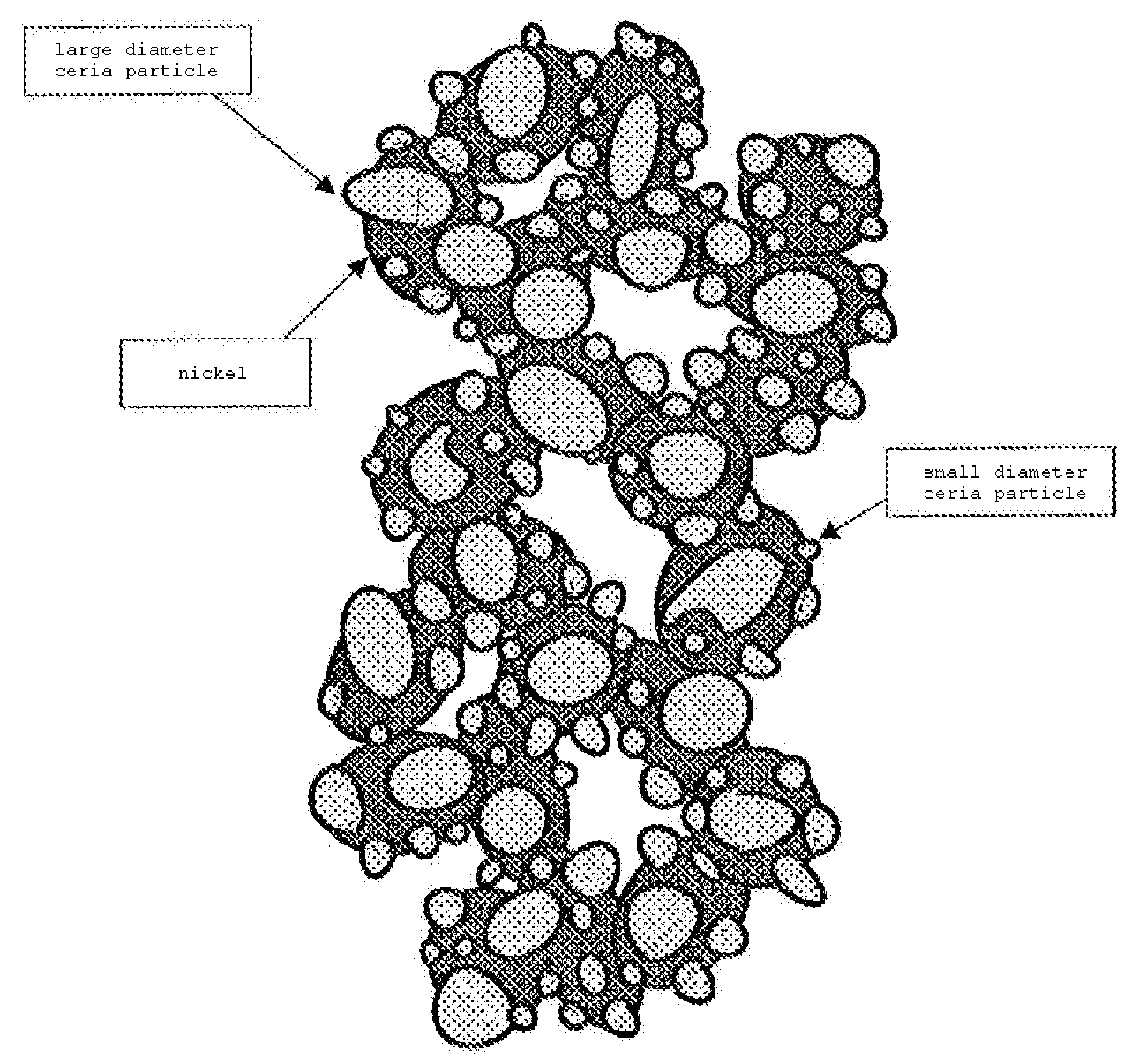
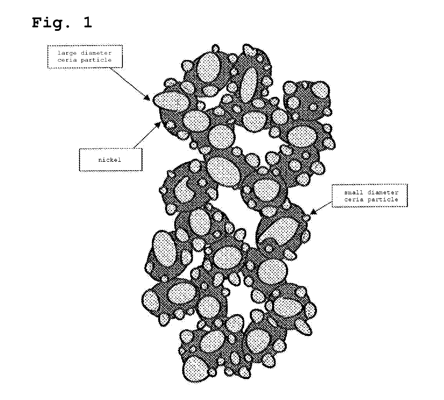
[0008](a) In an anode having a structure where B-doped ceria is attached to a surface of nickel of a porous frame structure in a particle form, when the amount of B-doped ceria particles, which are separately attached while the B-doped ceria particle is not in contact with the adjacent B-doped ceria particle, is large, characteristics of the solid electrolyte fuel cell are improved. (b) As shown in FIG. 1, when the B-doped ceria particles, which are separately attached to the surface of nickel of the porous frame structure, include B-doped ceria particles, which are known in the art and have an average particle size of 0.2 to 0.6 μm (hereinafter, referred to as “large diameter ceria particle”), and B-doped ceria particles, which have an average particle size of 0.01 to 0.09 μm (hereinafter, referred to as “small diameter ceria particle”) and are separately attached between the large diameter ceria particles, it is possible to improve characteristics of the solid electrolyte fuel cell.
[0046]A solid oxide fuel cell having a power generation cell, in which an anode of the aspect of the invention is provided, is capable of being operated at low temperatures, and it is possible to realize compactness and high efficiency of a generating module of the fuel cell.

Problems solved by technology

Since a current solid electrolyte fuel cell has a large size and has an insufficient output, there are demands for size reduction and high output.

Method used


Image

  • Power generation cell for solid electrolyte fuel cell
  • Power generation cell for solid electrolyte fuel cell
  • Power generation cell for solid electrolyte fuel cell

Examples


example 1

[0053]First, a method of preparing a crude material used to produce a power generation cell will be described.

[0054](a) Production of Lanthanum Gallate-Based Electrolyte Crude Powder:

[0055]Reagent-level pulverulent bodies of lanthanum oxide, strontium carbonate, gallium oxide, magnesium oxide, and cobalt oxide were prepared, weighed so as to form a composition expressed by (La0.8Sr0.2) (Ga0.8Mg0.15Co0.05)O3, mixed using a ball mill, and heated at 1350° C. for 3 hours in the air to form lumps of sintered bodies. The sintered body was coarsely pulverized using a hammer mill, and finely pulverized using the ball mill to produce lanthanum gallate-based electrolyte crude powder having the average particle size of 1.3 μm.

[0056](b) Production of an Ethanol Solution Containing Ultrafine Samarium-Doped Ceria (Hereinafter, Referred to as SDC) Powder:

[0057]1 mol / L sodium hydroxide aqueous solution was dropped on a mixed aqueous solution of 8 parts of 0.5 mol / L cerium nitrate aqueous solution a...

example 2

[0078]

[0079]Production of Lanthanum Gallate-Based Solid Electrolyte Crude Powder:

[0080]Reagent-level pulverulent bodies of lanthanum oxide, strontium carbonate, gallium oxide, magnesium oxide, and cobalt oxide were prepared, weighed so as to form a composition expressed by (La0.8Sr0.2) (Ga0.8Mg0.15Co0.05)O3, mixed using a ball mill, and heated at 1350° C. for 3 hours in the air to form lumps of sintered bodies. The sintered body was coarsely pulverized using a hammer mill, and finely pulverized using a ball mill to produce lanthanum gallate-based solid electrolyte crude powder having an average particle size of 1.3 μm.

[0081]Production of an Ethanol Solution Containing Ultrafine Samarium-Doped Ceria Powder:

[0082]Next, 1 mol / L sodium hydroxide aqueous solution was dropped on a mixed aqueous solution of 8 parts of 0.5 mol / L cerium nitrate aqueous solution and 2 parts of 0.5 mol / L samarium nitrate aqueous solution while the mixed aqueous solution was agitated to coprecipitate cerium oxi...

example 3

[0108]The nickel oxide powder prepared in example 2 was mixed with the SDC powder in the volume ratio of 10:90, and the resulting mixture was mixed with the organic binder solution, in which polyvinyl butyral and N-dioctyl phthalate were dissolved in the toluene-ethanol solvent, to form slurry. The slurry was applied on a side of the lanthanum gallate-based solid electrolyte using the screen printing method so that the average thickness was 1 μm, and dried to form a first green layer.

[0109]Furthermore, the nickel oxide powder was mixed with the ethanol solution containing the ultrafine SDC powder so that the volume ratio of nickel oxide to SDC was 35:65, and the resulting mixture was mixed with the organic binder solution, in which polyvinyl butyral and N-dioctyl phthalate were dissolved in the toluene-ethanol solvent, to form slurry. A slurry layer was formed on the dried first green layer through the screen printing method using the slurry so that the thickness was 1 μm, and dried...


PUM

PropertyMeasurementUnit
particle sizeaaaaaaaaaa
diameteraaaaaaaaaa
thicknessaaaaaaaaaa

Abstract

Provided is a power generation cell for a solid electrolyte fuel cell, in which a lanthanum gallate-based electrolyte is used as a solid electrolyte. Use of alternative energy for replacing petroleum can be promoted and it is possible to use waste heat using the solid electrolyte fuel cell, thus the solid electrolyte fuel cell is watched in views of resource nursing and the environment. The power generation cell is typically operated at 800 to 1000° C. However, currently, the power generation cell, which is operated at 600 to 800° C. by using the lanthanum gallate-based electrolyte, is suggested. Since a current power generation cell has a large size and has an insufficient output, there are demands for size reduction and high output. In the power generation cell, Sm-doped ceria particles are separately attached to a surface of porous nickel having a network frame structure. The demands are satisfied by using the anode.

Description

CROSS-REFERENCE TO PRIOR APPLICATION[0001]This is a U.S. National Phase Application under 35 U.S.C. §371 of International Patent Application No. PCT / JP2004 / 016658, filed Nov. 10, 2004, and claims the benefit of Japanese Patent Application Nos. 2003-379477, filed Nov. 10, 2003 and 2003-379791, filed Nov. 10, 2003, all of which are incorporated by reference herein. The International Application was published in Japanese on May 19, 2005 as International Publication No. WO 2005 / 045962 under PCT Article 21(2).TECHNICAL FIELD[0002]The present invention relates to a power generation cell for a solid electrolyte fuel cell, in which a lanthanum gallate-based electrolyte is used as a solid electrolyte and, more particularly, to an anode of a power generation cell for a solid electrolyte fuel cell.BACKGROUND ART[0003]Generally, in a solid electrolyte fuel cell, hydrogen gas, natural gas, methanol, coal gas or the like is used as fuel, thus use of alternative energy for replacing petroleum may ...

Claims


Application Information

Patent Timeline
Patent Type & Authority Applications(United States)
IPC IPC(8): H01M4/86H01M8/02H01M8/10H01M4/90H01M8/12
CPCH01M4/8605H01M4/8652H01M4/90H01M4/9041H01M4/9066Y02E60/525H01M8/1246H01M2004/8684H01M2008/1293Y02E60/521H01M4/9075Y02E60/50Y02P70/50
Inventor YAMADA, MASAHARUHOSHINO, KOJIADACHI, KAZUNORIKOMADA, NORIKAZU
Owner MITSUBISHI MATERIALS CORP
Learn More