Method for manufacturing polyimide-based carbon nanofiber electrode and/or carbon nanotube composite electrode and CDI apparatus using the electrode

Inactive Publication Date: 2009-04-30
SAMSUNG ELECTRONICS CO LTD
View PDF2 Cites 29 Cited by
  • Summary
  • Abstract
  • Description
  • Claims
  • Application Information

AI Technical Summary

Benefits of technology

[0018]In attempts to solve the problems of the prior art, one object of the present invention is to provide a method for manufacturing a polyimide carbon nanofiber electrode and/or a carbon nanotube composite electrode, wherein the diameters of carbon nanofibers can be lessened by optimizing the electrostatic spinning in order to improve spinnability.
[0019]Another aspect of the present invent

Problems solved by technology

Due to the high diameter, the carbon fibers have a low flexural strength and are not thus easy to apply to compress processing.
In spite of these advantages, polyimide has limited applications.
The reason is that polyimide has poor processability into a specific shape due to solvent-insolubility and heat resistance (flame resistance).
However, these conventional methods for preparing polyimide by electrostatic spinning and manufacturing for a supercapacitor electrode material from activated carbon nanofibers have disadvantages in that electrostatic spinning cannot be sm

Method used


Image

  • Method for manufacturing polyimide-based carbon nanofiber electrode and/or carbon nanotube composite electrode and CDI apparatus using the electrode
  • Method for manufacturing polyimide-based carbon nanofiber electrode and/or carbon nanotube composite electrode and CDI apparatus using the electrode
  • Method for manufacturing polyimide-based carbon nanofiber electrode and/or carbon nanotube composite electrode and CDI apparatus using the electrode

Examples


Embodiment Construction

[0046]Reference will now be made in detail to the embodiments of the present invention, examples of which are illustrated in the accompanying drawings, wherein like reference numerals refer to the like elements throughout. The embodiments are described below to explain the present invention by referring to the figures.

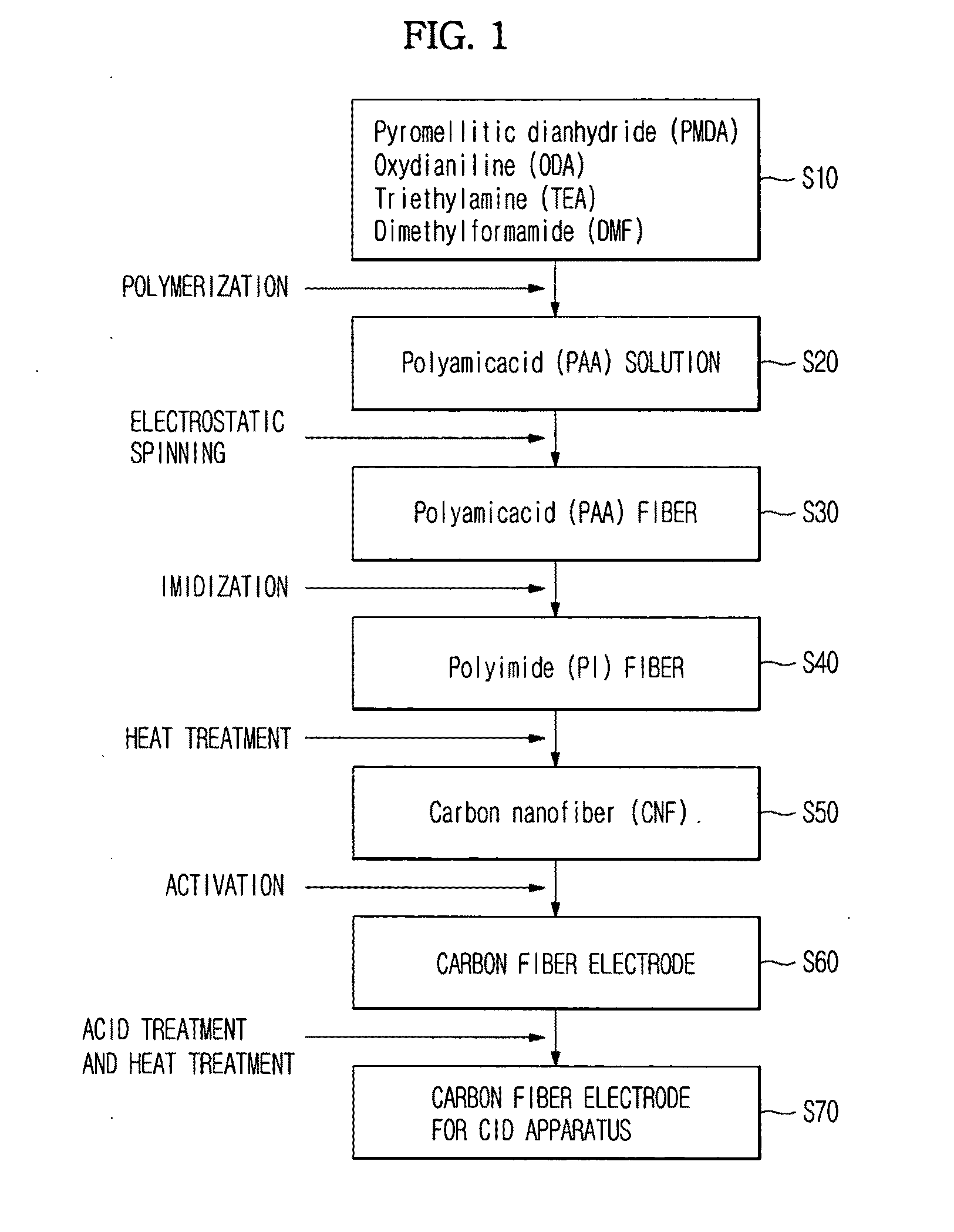
[0047]FIG. 1 is a flow chart illustrating a method to manufacture a carbon fiber electrode according to a preferred embodiment of the present invention.

[0048]First, in order to synthesize polyamic acid (PAA) as a polyimide (PI) precursor, 4 g of oxydianiline (ODA) is dissolved in 20 g of dimethylformamide (DMF). After the resulting solution is allowed to stand at 5° C., 4.4 g of pyromellitic dianhydride (PMDA) is slowly added thereto over 30 minutes with stirring, to obtain the targeted polyamic acid (PAA).

[0049]In this embodiment, the weights of ODA, DMF and PMD are not intended to be restricted to the aforementioned specific values and are given for illustrating one ...


PUM

PropertyMeasurementUnit
Percent by massaaaaaaaaaa

Abstract

A method to manufacture a carbon fiber electrode comprises synthesizing polyamic acid (PAA) as a polyimide (PI) precursor from pryomellitic dian hydride (PMDA) and oxydianiline (ODA) as monomers and triethylamine (TEA) as a catalyst, adding dimethylformamide (DMF) to the polyamic acid (PAA) solution to prepare a spinning solution and subjecting the spinning solution to electrostatic spinning at a high voltage to obtain a PAA nanofiber paper, converting the PAA nanofiber paper into a polyimide (PI) nanofiber paper by heating, and converting the polyimide (PI) nanofiber paper into a carbon nanofiber (CNF) paper by heating under an Ar atmosphere. Also, the method to manufacture a polyimide carbon nanofiber electrode and/or a carbon nanotube composite electrode may utilize carbon nanofibers having diameters that are lessened by optimizing electrostatic spinning in order to improve spinnability.

Description

CROSS-REFERENCE TO RELATED APPLICATIONS[0001]This application claims the benefit of Korean Patent Application No. 2007-0107256, filed on Oct. 24, 2007 in the Korean Intellectual Property Office, the disclosure of which is incorporated herein by reference.BACKGROUND[0002]1. Field[0003]The present invention relates to a method for manufacturing a polyimide carbon nanofiber electrode and / or a carbon nanotube composite electrode, and a CDI apparatus using the electrode. More specifically, the present invention relates to a method for manufacturing a flat plate electrode from polyimide carbon nanofibers without using any binder and a CDI apparatus using the flat plate electrode.[0004]2. Description of the Related Art[0005]Generally, carbon fibers and activated carbon fibers are classified into polyacrylonitrile (PAN)-based, acryl-based, pitch-based, phenol-based carbon fibers, etc., depending on the starting material to make the fibers.[0006]Carbon fibers are prepared using wet-, melt- o...

Claims


Application Information

Patent Timeline
IPC IPC(8): B01D57/00B29C47/00
CPCB82Y30/00Y10S977/844C02F2001/46133C02F2001/46152C02F2201/4617C04B35/83C04B2235/5264C04B2235/5288D01D5/0038D01F1/10D01F6/74D01F9/24H01M4/583H01M4/96Y02E60/50Y02E60/12C02F1/4695Y02E60/10
Inventor PARK, DAE WOOKNOH, HYONG SOONOJIMA, HIDEONGUYEN, THI XUYENSONG, CHUL HOLEE, YOUNG HEE
Owner SAMSUNG ELECTRONICS CO LTD
Why Eureka
Try Eureka