
High dielectric polymer composite

Inactive Publication Date: 2009-05-14
SAMSUNG ELECTRO MECHANICS CO LTD
View PDF4 Cites 22 Cited by
  • Summary
  • Abstract
  • Description
  • Claims
  • Application Information

AI Technical Summary

Benefits of technology

[0009]It is therefore desirable to achieve a high dielectric constant by use of the PTF process. Accordingly, disclosed herein is, in an embodiment, a high dielectric polymer composite having a high dielectric constant and a low heat loss.

Problems solved by technology

However, with the advancement of the miniaturization of passive devices, the manufacture and mounting thereof become more difficult, and thus the conventional process has many limitations.
However, in the case of the capacitor, it cannot be applied to fields requiring a high capacity, because a material having high capacitance and a manufacturing process for applying the material to a low-temperature process (i.e., less than about 260° C.) are not available.
Furthermore, the produced ceramic thin film may easily break down when applied to an organic substrate.
Further, the application to FR-4 or flex substrates is also limited, causing high cost of the manufacturing process.
In contrast, the PTF process may be easily and inexpensively performed and may ensure high applicability to an organic substrate, but results in low dielectric capacity.

Method used


Image

  • High dielectric polymer composite
  • High dielectric polymer composite
  • High dielectric polymer composite

Examples


example 2

Preparative Example 2

i) Synthesis of Tail Portion

[0064]The composition ratio of polyethylene glycol methacrylate, hexyl methacrylate and glycidyl methacrylate was set to 1:1:1. For the synthesis of a tail portion as a block copolymer having an expected number averaged molecular weight of 2,000, an initiator, for example, methyl trimethylsilyl dimethylketene acetal (3.48 g, 20 mmol), and a catalyst, for example, tetrabutylammonium-3-chlorobenzoate (0.07 g, 0.17 mmol), were dissolved in acetonitrile (1 ml) and THF (10 ml). Then, this solution was placed in a round-bottom flask and then stirred for 30 minutes using magnetic stirring bars. The stirred solution was slowly added with monomers, for example, polyethyleneglycol methacrylate (6.603 g, 7.5 mmol), hexyl methacrylate (4.569 g, 7.5 mmol) and glycidyl methacrylate (3.816 g, 7.5 mmol), and then allowed to react for 7 hours. After that, the disappearance of the monomers was confirmed through gas chromatography.

ii) Introduction of He...

example 1

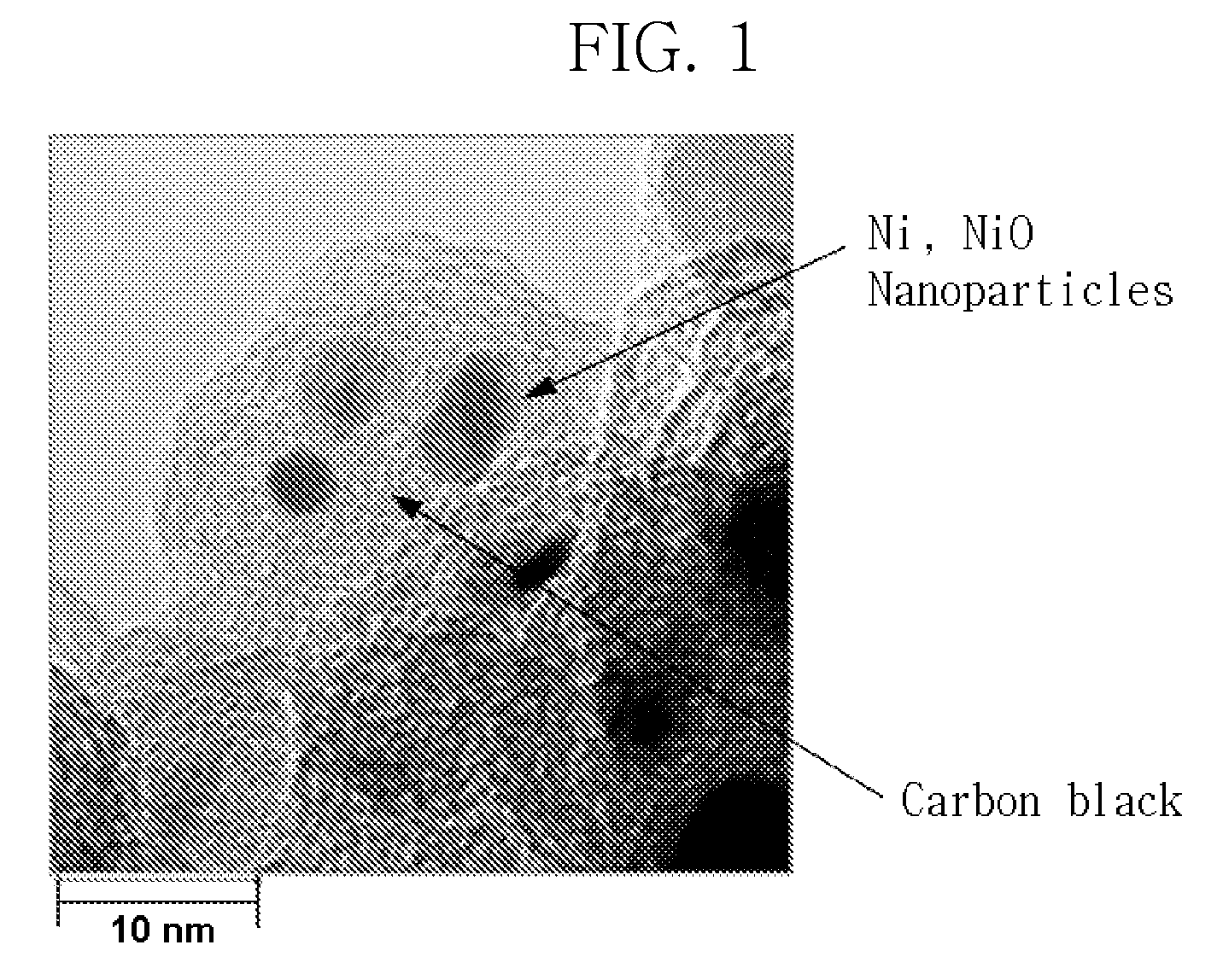
[0066]0.268 g of the carbon black prepared as above in Preparative Example 1 and 0.072 g of the surfactant prepared as above in Preparative Example 2 were mixed with 1.557 g of 3,4-epoxycyclohexylmethyl-3,4-epoxycyclohexanecarboxylate (Aldrich), 1.051 g of hexahydro-4-methylphthalic anhydride (Aldrich), and 0.005 g of 1-methylimidazole (Aldrich), to thereby preparing a paste.


PUM


Abstract

A high dielectric polymer composite having a high dielectric constant is disclosed herein. The high dielectric polymer composite includes a conductive material doped with oxidizable metal nanoparticles or metal oxide nanoparticles to decrease dielectric loss, and a surfactant having a head portion containing an acidic functional group to form a passivation layer that surrounds the conductive material, resulting in increased dielectric constant.

Description

[0001]This application claims priority to Korean Patent Application No. 2007-115981, filed on Nov. 14, 2007, and all the benefits accruing therefrom under 35 U.S.C. § 119, the content of which is incorporated herein by reference in its entirety.BACKGROUND OF THE INVENTION[0002]1. Field of the Invention[0003]This disclosure is directed to a high dielectric polymer composite, and more particularly, to a high dielectric polymer composite, which comprises a conductive material doped with oxidizable metal nanoparticles or metal oxide, a surfactant having a head portion containing an acidic functional group, and a polymer resin, thus realizing a high dielectric constant.[0004]2. Description of the Related Art[0005]According to recent trends in electronic products industry, mobile electronics are dominating technological development and markets. Thus, intensive and extensive research and development have been made to decrease the size and weight of mobile products and increase the performa...

Claims


Application Information

Patent Timeline
IPC IPC(8): H01B1/00
CPCB82Y10/00H01G4/206H01G4/33H05K1/162H05K2201/0323H05K2201/0215H05K2201/0257H05K2201/026H05K2201/0209B82Y30/00H01B1/22H01B3/10
Inventor LEE, EUN SUNGLEE, SANG MOCKBYUN, YOUNG HUN
Owner SAMSUNG ELECTRO MECHANICS CO LTD
Learn More