Electro-optic assemblies, and adhesives and binders for use therein

a technology of electrophoretic assemblies and adhesives, applied in the direction of optical elements, film/foil adhesives, instruments, etc., can solve the problems of inadequate service life of these displays, gas-based electrophoretic media is susceptible to the same types of problems, and the use of these assemblies is prevented. to achieve the effect of reducing the volume resistivity of the polymeric adhesive material

Inactive Publication Date: 2009-05-14
E INK CORPORATION
View PDF99 Cites 167 Cited by
  • Summary
  • Abstract
  • Description
  • Claims
  • Application Information

AI Technical Summary

Benefits of technology

[0043]Accordingly, in one aspect this invention provides an electro-optic assembly comprising an adhesive layer and a layer of electro-optic material, the adhesive layer comprising a polymeric adhesive material and an ionic material, the ionic material having one of its cation and anion fixed to the polymeric adhesive material and the other of its cation and anion free to migrate through the polymeric adhesive material, the ionic material reducing the volume resistivity of the polymeric adhesive material and not being removed by heating the polymeric adhesive material to about 50° C.

Problems solved by technology

Nevertheless, problems with the long-term image quality of these displays have prevented their widespread usage.
For example, particles that make up electrophoretic displays tend to settle, resulting in inadequate service-life for these displays.
Such gas-based electrophoretic media appear to be susceptible to the same types of problems due to particle settling as liquid-based electrophoretic media, when the media are used in an orientation which permits such settling, for example in a sign where the medium is disposed in a vertical plane.
Indeed, particle settling appears to be a more serious problem in gas-based electrophoretic media than in liquid-based ones, since the lower viscosity of gaseous suspending fluids as compared with liquid ones allows more rapid settling of the electrophoretic particles.
However, the methods used for assembling LCD's cannot be used with solid electro-optic displays.
This LCD assembly process cannot readily be transferred to solid electro-optic displays.
Electro-optic displays are often costly; for example, the cost of the color LCD found in a portable computer is typically a substantial fraction of the entire cost of the computer.
As discussed in the aforementioned U.S. Pat. Nos. 7,012,735 and 7,173,752, the selection of a lamination adhesive for use in an electro-optic display (or in a front plane laminate, inverted front plane laminate, double release film or other sub-assembly used to produce such an electro-optic display) presents certain peculiar problems.
However, in practice it is not possible to vary the conductivity of the polyurethane by controlling the proportions of the materials used in its manufacture.
As a result, the polyurethane adhesive is not sufficiently conductive for use in many electro-optic displays and electro-optic assemblies, and it known to increase its conductivity by doping it with salts or other materials, as described in the aforementioned U.S. Pat. Nos. 7,012,735 and 7,173,752.
Unfortunately, it has been found that adhesives formulated in this manner can damage active matrix backplanes comprising transistors made from certain organic semiconductors.

Method used


Image

  • Electro-optic assemblies, and adhesives and binders for use therein
  • Electro-optic assemblies, and adhesives and binders for use therein

Examples


example 1

Synthesis of TMXDI-PPO Polyurethane with Tetrabutylammonium Hydroxide Neutralization

[0083]The polyurethane prepared in this Example is similar to the prior art polyurethane produced in Example 2 below, except that it has a higher acid content.

[0084]A prepolymer was prepared in a three-necked round bottom flask equipped with a magnetic stirrer, a condenser, and a nitrogen inlet. The reaction was carried out under nitrogen. Tetramethylxylene diisocyanate (TMXDI, supplied by Aldrich Chemical Company, 16.34 g, 0.067 mole), poly(propylene glycol) diol (supplied by Aldrich Chemical Company, average Mn ca. 2000, 33.5 g, 0.0168 mole), and dibutyltin dilaurate (supplied by Aldrich Chemical Company, 0.04 g) were charged into the flask and the mixture was heated at 90° C. in an oil bath for 2 hours. Afterwards, a solution of 2,2-bis(hydroxymethyl)propionic acid (from Aldrich, 3.35 g, 0.025 mol) in 1-methyl-2-pyrrolidinone (from Aldrich, 8.5 g) was added to the flask and the reaction allowed to...

example 2

Synthesis of TMXDI-PPO Polyurethane with Triethylamine Neutralization (Control)

[0085]Example 1 was repeated up to the point at which an NCO-terminated prepolymer was obtained and the temperature of the reaction mixture lowered to 70° C. Thereafter triethylamine (from Aldrich, 2.4 g, 0.0237 mole) was added slowly over a period of 30 minutes to neutralize the carboxylic acid. The reaction mixture was then slowly added to de-ionized water (100 g) at 35° C. in a jacketed 500 mL glass reactor under mechanical stirring and nitrogen atmosphere to convert the prepolymer to a water-borne dispersion. The chain extension reaction and the final heating of the dispersion to 50° C. were carried out in the same manner as in Example 1.

example 3

Preparation of Experimental Single Pixel Displays from the Materials Prepared in Examples 1 and 2

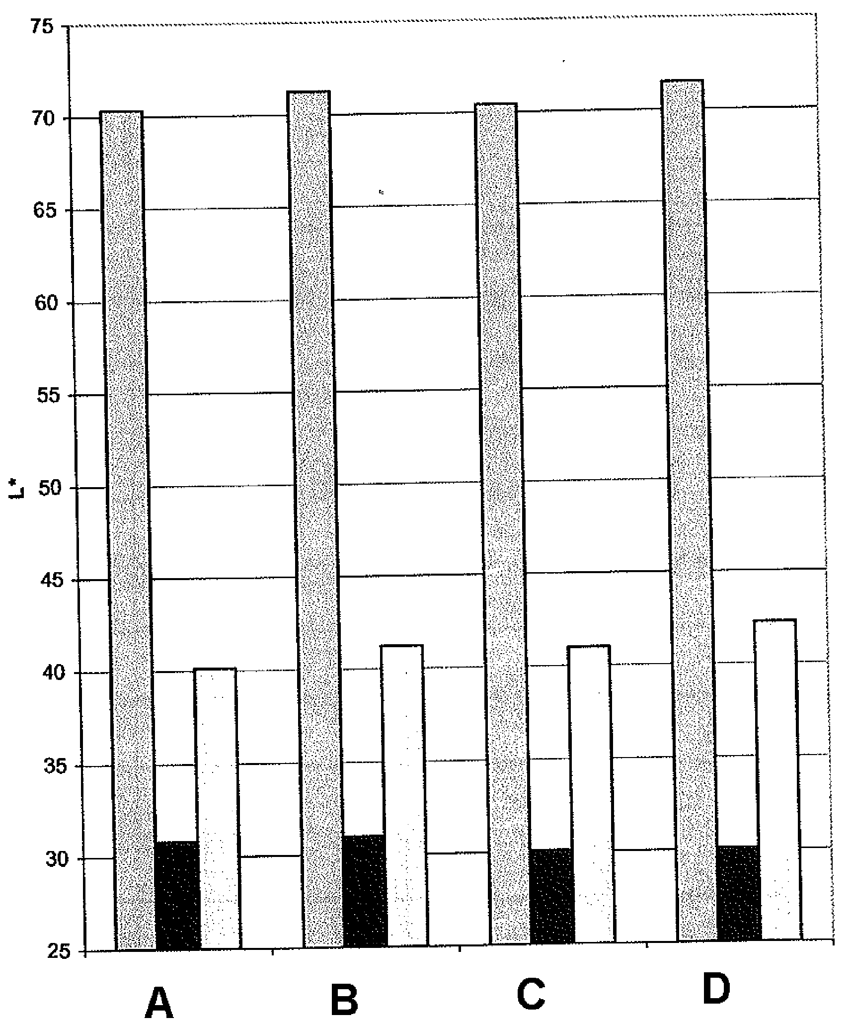
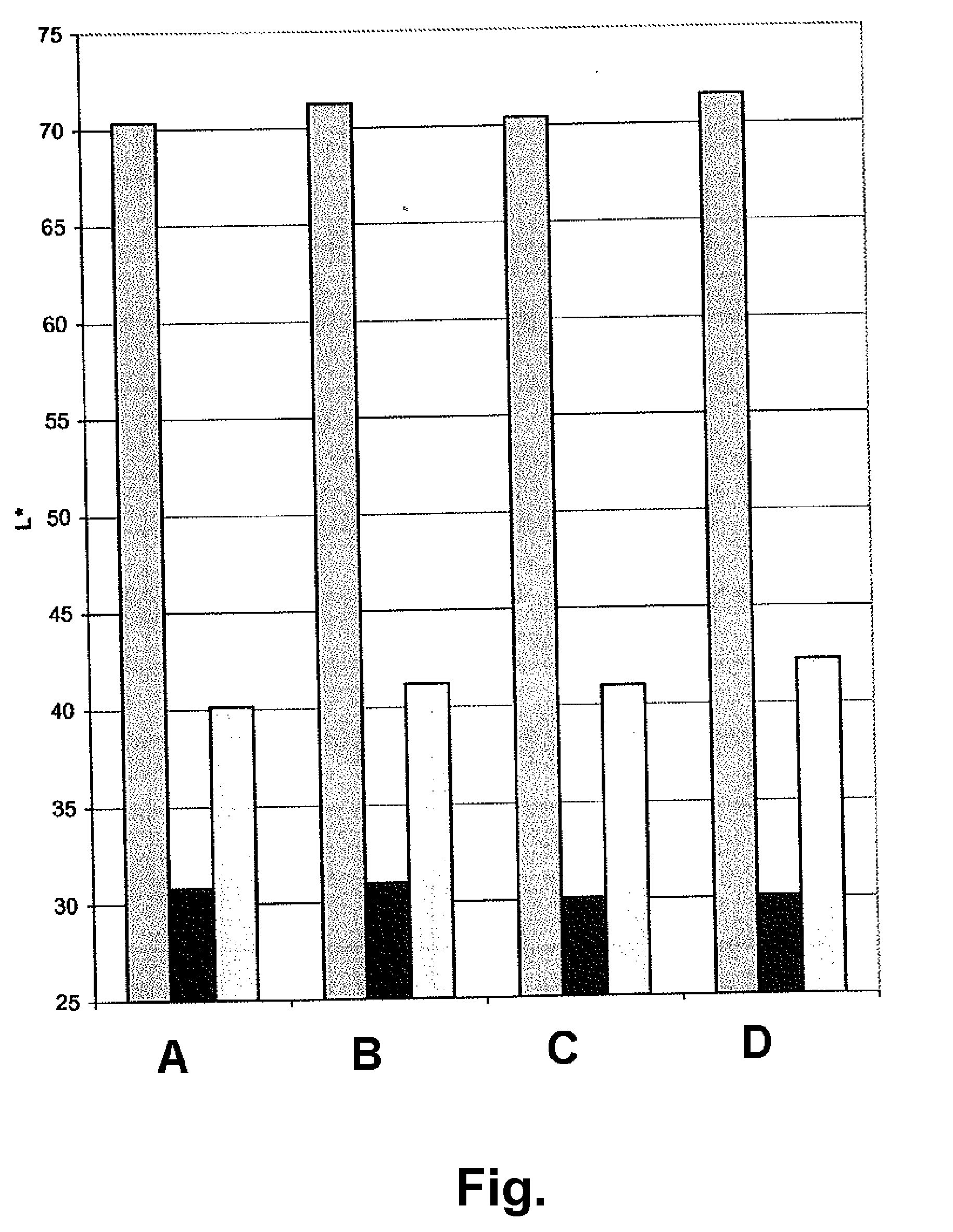
[0086]The polyurethanes prepared in Examples 1 and 2 above were separately coated on to metallized release film in a (dried) thickness of about 20 μm. Drying of the coated polymeric films was carried out in a belt-transport drying oven at 60° C. and a transport rate of 1 ft / min (about 5.1 mm / sec); these conditions are known to reduce the content of NMP to a very low level. Separately, an electrophoretic medium was prepared substantially as described in Example 4 of U.S. Pat. No. 7,002,728 and coated on to the indium tin oxide (ITO) coated surface of a 5 mil (127 μm) poly(ethylene terephthalate) (PET) film coated on one surface with ITO. The two sub-assemblies were laminated to each other with the electrophoretic layer in contact with the lamination adhesive to form a front plane laminate as described in the aforementioned U.S. Pat. No. 6,982,178. The release sheet was peeled from the fr...


PUM

PropertyMeasurementUnit
diameteraaaaaaaaaa
thicknessaaaaaaaaaa
thicknessaaaaaaaaaa

Abstract

An electro-optic assembly comprises an adhesive layer and a layer of electro-optic material. The adhesive layer comprises a polymeric adhesive material and an ionic material having either its cation or its anion fixed to the polymeric adhesive material. The ionic material reduces the volume resistivity of the polymeric adhesive material and is not removed upon heating to 50° C. In a similar electro-optic assembly comprising an adhesive layer and a layer of electro-optic material, the adhesive layer comprises a polymeric adhesive material which has been subjected to dialysis or diafiltration to remove organic species having a molecular weight less than about 3,500, so that the adhesive material has a content of N-methylpyrrolidone not exceeding 500 ppm based upon the total weight of the adhesive layer and layer of electro-optic material.

Description

REFERENCE TO RELATED APPLICATIONS[0001]This application claims benefit of copending Application Ser. No. 60 / 987,876, filed Nov. 14, 2007.[0002]This application is also related to:[0003](a) U.S. Pat. No. 7,012,735;[0004](b) U.S. Pat. No. 7,173,752; and[0005](c) copending Application Ser. No. 61 / 052,427, filed May 12, 2008.[0006]The entire contents of these patents and copending applications, and of all other U.S. patents and published and copending applications mentioned below, are herein incorporated by reference.BACKGROUND OF INVENTION[0007]This invention relates to electro-optic assemblies useful in the production of electro-optic displays, and to adhesives and binders for use in such assemblies. More specifically, this invention provides adhesive and binder compositions having controlled volume resistivity, and electro-optic assemblies and displays incorporating such adhesives. The adhesives disclosed herein may be useful in applications other than electro-optic displays.[0008]El...

Claims


Application Information

Patent Timeline
Patent Type & Authority Applications(United States)
IPC IPC(8): G02F1/167
CPCC08G18/0823C08G18/12G02F2202/28C08G18/6692C08G18/765C08G2170/80C08K5/0075C08K5/19C08K5/49C09J7/0207C09J9/02C09J175/04C09J2205/102C09J2475/00G02F1/1334G02F1/167C08G18/3206C09J7/38C09J2203/318C09J2301/408B32B7/12C09J11/08G02F1/1681C09D5/4465G02F1/1533C08G18/0814C08G18/10C08G18/4825
Inventor WHITESIDES, THOMAS H.CAO, LAN
Owner E INK CORPORATION
Why Eureka
Try Eureka