Electrolytic Capacitor Anode Treated with an Organometallic Compound
- Summary
- Abstract
- Description
- Claims
- Application Information
AI Technical Summary
Benefits of technology
Problems solved by technology
Method used
Image
Examples
example 1
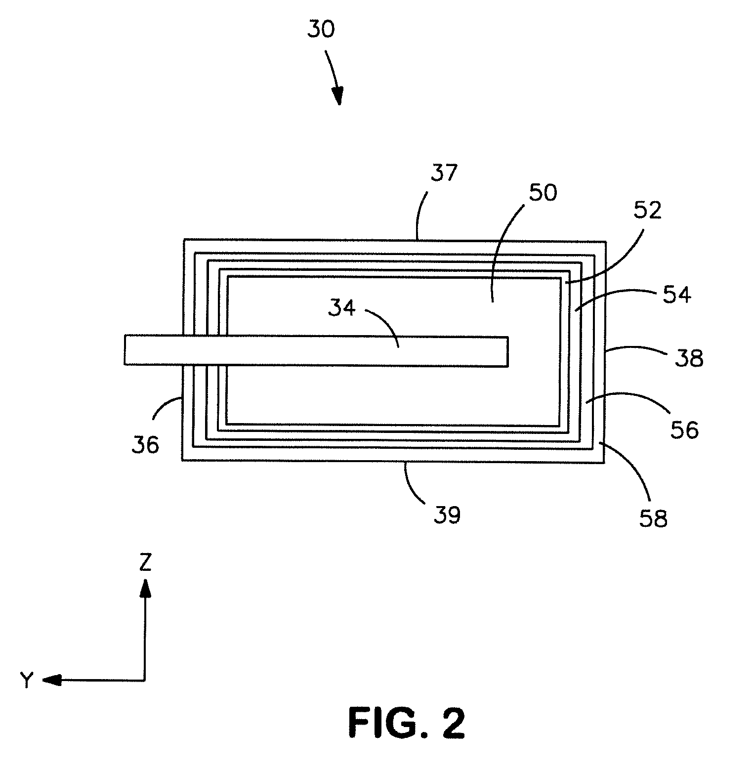
[0038]80,000 μFV / g niobium oxide powder (HC Starck) was pressed into pellets and sintered to form a porous electrode body. Anodic oxidation was then carried out in an aqueous solution containing phosphoric acid and varying concentrations of N-2-(aminoethyl)3-aminopropylmethyldimethoxysilane (0%, 0.2%, 1%, and 5%) at ambient temperature. The anodic oxidation was done first galvanostatically to the desired voltage and than potentiostatically. The conductivity of the electrolyte with supporting electrolyte was 4.5 mS / cm. The voltage was chosen to obtain a targeted capacitance of 100 μF. After anodic oxidation, the pellets were coated with a manganese dioxide layer, a graphite coating and a silver coating. The finished parts were completed by conventional assembly technology to the B case (EIA 3528). The V-A characteristics of a capacitor were then measured. The results are shown in FIG. 5.
example 2
[0039]Anode pellets were formed as described in Example 1, except that anodic oxidation occurred in an aqueous solution that contained 1% N-2-(aminoethyl)3-aminopropylmethyidimethoxysilane at temperatures of 22° C. and 60° C. The V-A characteristics are shown in FIG. 6.
example 3
[0040]Anode pellets were formed as described in Example 1, except that anodic oxidation occurred in a solution containing water and ethanol solvents and 1% N-2-(aminoethyl)3-aminopropylmethyldimethoxysilane. The V-A characteristics are shown in FIG. 7.
PUM
| Property | Measurement | Unit |
|---|---|---|
| Fraction | aaaaa | aaaaa |
| Fraction | aaaaa | aaaaa |
| Electrical conductivity | aaaaa | aaaaa |
Abstract
Description
Claims
Application Information
 - R&D
- Intellectual Property
- Life Sciences
- Materials
- Tech Scout
- Unparalleled Data Quality
- Higher Quality Content
- 60% Fewer Hallucinations
Browse by: Latest US Patents, China's latest patents, Technical Efficacy Thesaurus, Application Domain, Technology Topic, Popular Technical Reports.
© 2025 PatSnap. All rights reserved.Legal|Privacy policy|Modern Slavery Act Transparency Statement|Sitemap|About US| Contact US: help@patsnap.com


