Energy-transmitting or ultraviolet light-transmitting optical fiber preform and production process thereof

a technology of energy-transmitting or ultraviolet light-transmitting optical fiber and production process, which is applied in the direction of glass making apparatus, manufacturing tools, instruments, etc., can solve the problems of low transmittance, great loss, and inability to transmit, and achieve excellent durability and low transmission loss

Inactive Publication Date: 2009-08-20
ASAHI GLASS CO LTD
View PDF0 Cites 55 Cited by
  • Summary
  • Abstract
  • Description
  • Claims
  • Application Information

AI Technical Summary

Benefits of technology

[0053]The optical fiber produced using the preform of the present invention becomes an energy-transmitting or ultraviolet light-transmitting optical fiber that has a low transmission loss when transmi...

Problems solved by technology

Therefore, the loss is great, and hence the transmission was impossible.
However, the ultraviolet light-transmitting optical fiber described in Patent Document 1 leaves the following problems to be solved.
A fiber having a small fiber diameter of about 200 μm has difficulties that the transmittance is low and the durability becomes deteriorated, depending on the fib...

Method used


Image

  • Energy-transmitting or ultraviolet light-transmitting optical fiber preform and production process thereof
  • Energy-transmitting or ultraviolet light-transmitting optical fiber preform and production process thereof

Examples


examples 1 to 3

[0151]Core materials and cladding materials were produced by a VAD method. The F concentration and OH concentration in each sample were adjusted by the F compound gas concentration, temperature, etc. at the time of treating a porous silica glass body with an F compound gas.

[0152]The produced core materials and cladding materials were processed by a peripheral grinding machine and a cylinder grinding machine and then polished with an abrasive grain for polishing GC #240, GC #400, FO #600, FO #800 and FO #1000 (trade names, produced by Fujimi Corp.) each formed into a slurry. Thereafter, precision polishing was performed using MIREK (trade name, produced by Mitsui Mining & Smelting Co., Ltd.). In the core materials and cladding materials after precision polishing, the non-circularity was 2 or less, the particle was 0.1 μm or less in diameter, and the scratch was 11 μm in width. Subsequently, precision cleaning was applied in place of a usual flame polishing step using oxyhydrogen flam...

example 4

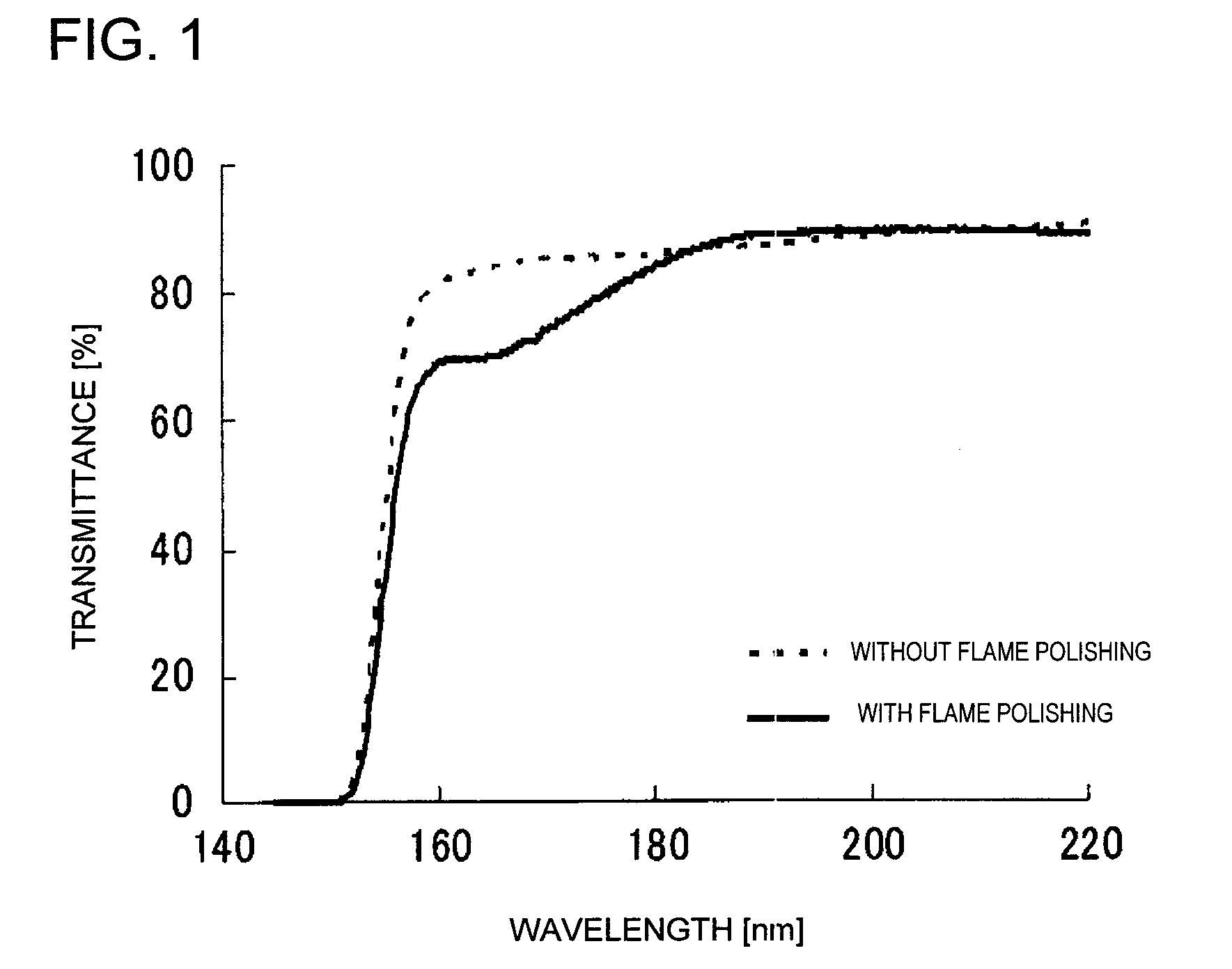
[0153]A core material and a cladding material were produced by a VAD method in the same manner as in Examples 1 to 3. The produced core material and cladding material each was subjected to usual polishing using alumina and cerium oxide and then to a flame polishing process using oxyhydrogen flame. The flame polishing of the cladding material was performed by a method of treating the outside with oxyhydrogen while allowing an oxygen gas to flow in the inside. Here, the temperature raise of the core material and the cladding material in the flame polishing step was measured with a radiation thermometer (Marathon MM-Model G5H, produced by Raytek Corporation). The measurement value was 2,000° C.

[0154]The dotted line in FIG. 1 shows the transmittance spectrum measured by making rays incident in the direction perpendicular to the side face of the core material of the sample not subjected to flame polishing (Example 1). The solid line in FIG. 1 shows the transmittance spectrum measured wit...

examples 5 to 8

[0163]A cladding was formed on the core materials of Examples 1 to 4 by using a VAD method to produce fiber preforms.

[0164]The measurement results (average) of the OH concentration, O2 concentration, ODC (I) concentration, ODC (II) concentration and F concentration in the core and cladding of each preform are shown in Table 5.

TABLE 5OHO2ODC (I)ODC (II)FConcentrationConcentrationConcentrationConcentrationConcentration(ppm)(molecules / cm3)(defects / cm3)(defects / cm3)(ppm)Example 5Core1≦1 × 10¹⁶≦1 × 10¹²≦1 × 1012300Cladding≦1≦1 × 10¹⁶≦1 × 10¹²≦1 × 10127500Example 6Core5≦1 × 10¹⁶≦1 × 10¹²≦1 × 1012200Cladding≦1≦1 × 10¹⁶≦1 × 10¹²≦1 × 10128300Example 7Core8≦1 × 10¹⁶≦1 × 10¹²≦1 × 1012150Cladding≦1≦1 × 10¹⁶≦1 × 10¹²≦1 × 101213500Example 8Core5  1 × 10¹⁷  8 × 10¹⁵  8 × 1015200Cladding≦1≦1 × 10¹⁶≦1 × 10¹²≦1 × 10128500

[0165]The measurement results (average) of the OH concentration, O2 concentration, ODC (I) concentration, ODC (II) concentration and F concentration in the regions of ±10 μm and ±20 ...


PUM

PropertyMeasurementUnit
Fractionaaaaaaaaaa
Fractionaaaaaaaaaa
Fractionaaaaaaaaaa

Abstract

The present invention is to provide an optical fiber preform suitable for the production of an energy-transmitting or ultraviolet light-transmitting optical fiber, which has an excellent transmittance of a high-energy light of 50 KW/cm2 or more in terms of laser peak power or an ultraviolet light, to be transmitted through the optical fiber and which exhibits excellent durability that causes almost no deterioration by the irradiation with those two lights; and a production process thereof. The present invention relates to an energy-transmitting or ultraviolet light-transmitting optical fiber preform, having a core and a cladding each comprising a silica glass, wherein the core has an average OH concentration of 0 to 10 ppm, an average O2 concentration of ≦1015 molecules/cm3, an average ODC (I) concentration of ≦1013 defects/cm3, an average ODC (II) concentration of ≦1012 defects/cm3 and an average F concentration of ≦1,000 ppm, and the cladding has an average OH concentration of 0 to 10 ppm, an average F concentration of ≧7,000 ppm, an average O2 concentration of ≦1016 molecules/cm3, an average ODC (I) concentration of ≦1013 defects/cm3 and an average ODC (II) concentration of ≦1012 defects/cm3.

Description

TECHNICAL FIELD[0001]The present invention relates to an energy-transmitting or ultraviolet light-transmitting optical fiber preform, particularly an optical fiber preform for transmitting ultraviolet light at a wavelength of 300 nm or shorter; a core material and a cladding material each used in the optical fiber preform; and a process for producing the optical fiber preform.BACKGROUND ART[0002]Conventionally, an optical fiber has been used, for example, in the field of medical equipment or for the production apparatus of a semiconductor as well as for the information-communication or the like. It is also employed for an excimer laser used in the lithography in the process of producing a semiconductor.[0003]The optical fiber is formed of a synthetic silica glass or the like, and is a product in which a cladding having a low refractive index is provided on the outer circumference of a core having a high refractive index. The core is doped with germanium, phosphorus or the like for r...

Claims


Application Information

Patent Timeline
IPC IPC(8): B32B17/06C03C3/06C03B37/075C03B37/10
CPCC03B37/01228C03B37/01453C03B37/01466C03B37/01861G02B6/102C03C3/06C03C2201/12C03C2201/23C03B2201/12
Inventor KUWAHARA, MADOKAKOIKE, AKIOOKADA, KANAMEOGAWA, TOMONORI
Owner ASAHI GLASS CO LTD
Why Eureka
Try Eureka