

High friction coating formulations and systems and coated articles thereof exhibiting radar signature reduction and methods of providing the same
a technology of radar signature and coating formulation, applied in the direction of electrically conductive paints, nuclear engineering, nuclear elements, etc., can solve the problems of inability to resist environmental weathering, inability to meet the requirements of traditional coating application processes used in ship construction and maintenance, and inability to meet the requirements of radar signature reduction, etc., to improve the stealth characteristics of a range of military vehicles and aircraft, improve the safety of topside ship deck operations, and high friction
- Summary
- Abstract
- Description
- Claims
- Application Information
AI Technical Summary
Benefits of technology
Problems solved by technology
Method used
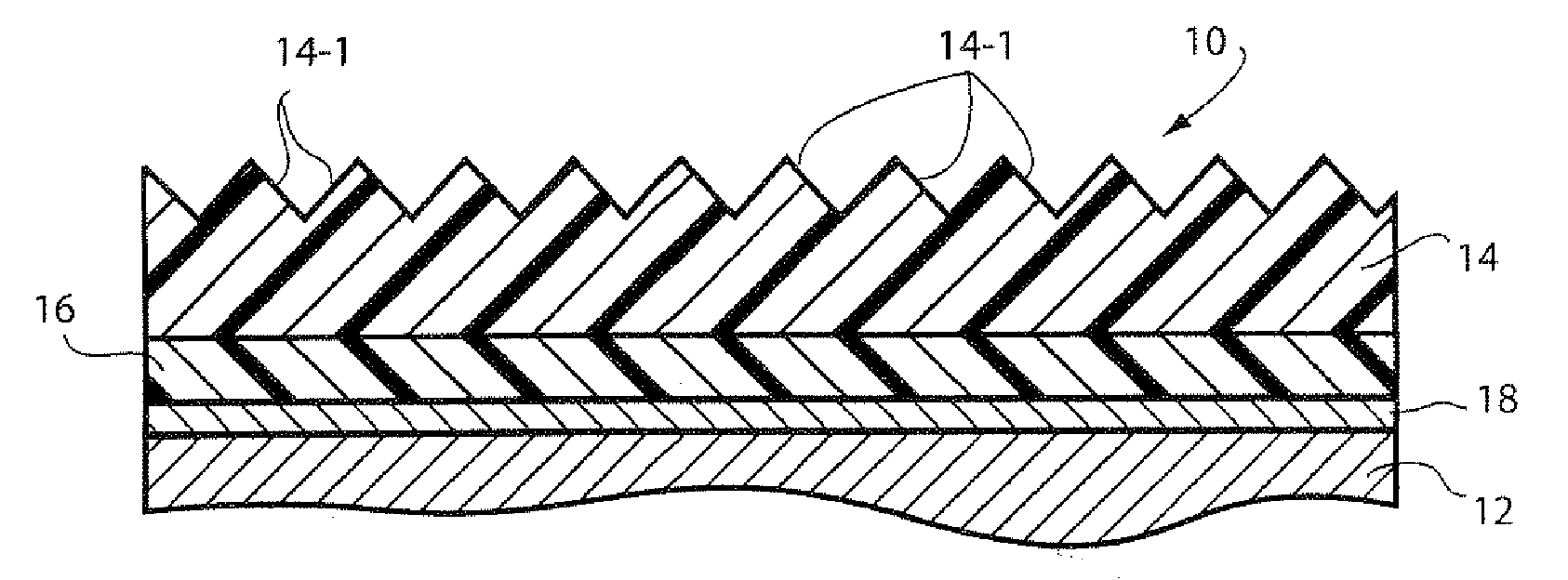
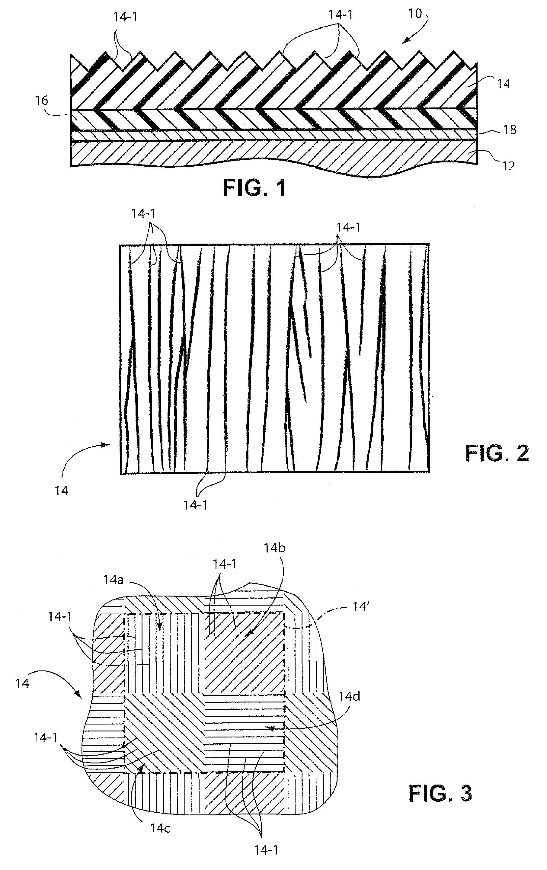
Image

Examples
example 1
Topcoat (Non-Skid) Formula No. T-1
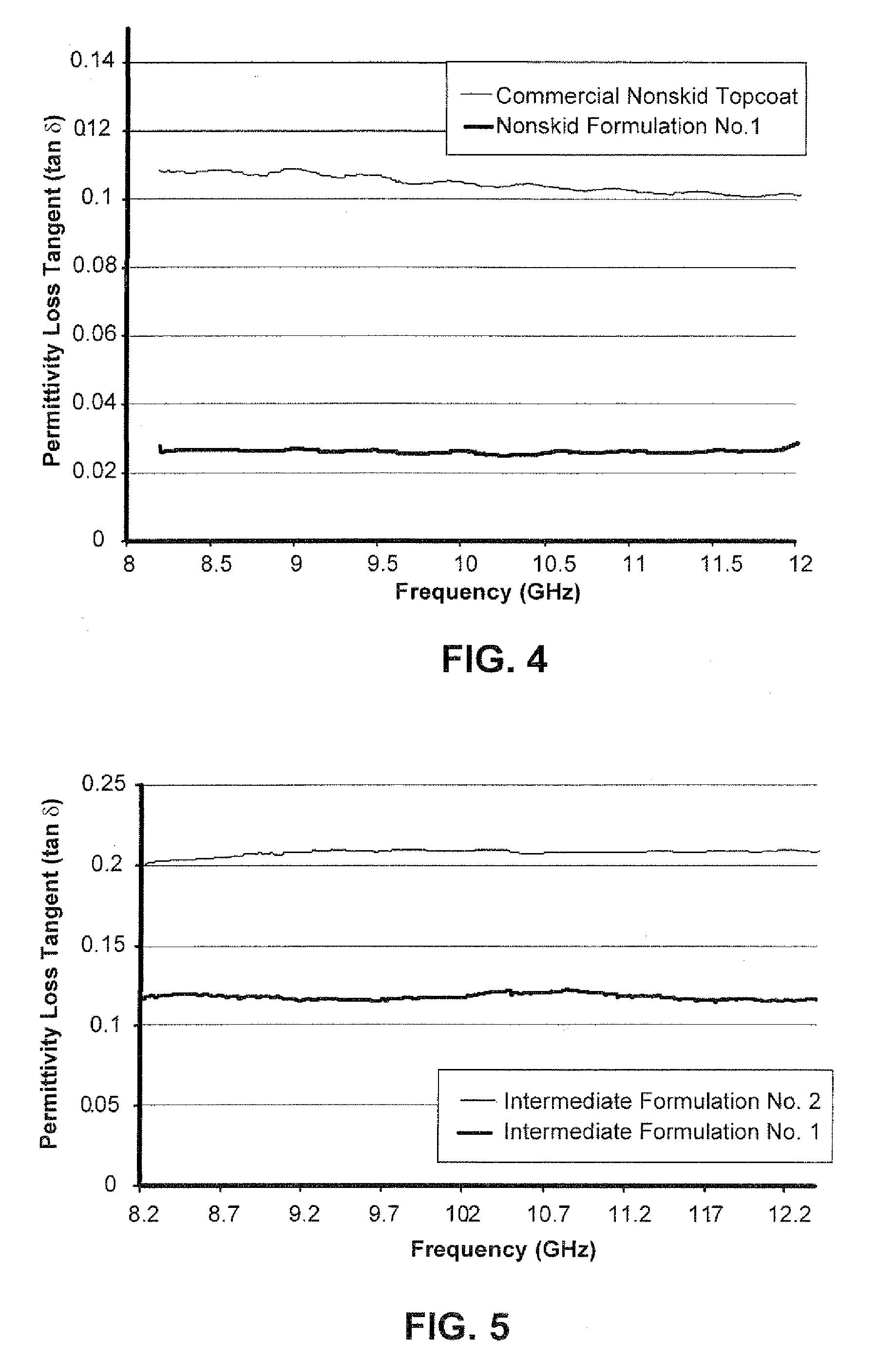
[0060](Example of optimal permittivity (∈′))
[0061]The following formulation was made as identified as Topcoat (Non-skid) Formula T-1 as described in Table 1 below:
TABLE 1Wt %Part A - BaseLiquid epoxy resin (e.g. Epon ™ 828)28.2%Thickening agent (e.g. Garamite ® 1958 by Southern1.4%Clay Products)Dielectric fillers (e.g. Zeeospheres ™ G200)24.6%Abrasion resistant media (e.g. Alodur ® alumina)39.8%n-butanol solvent6.0%Part BModified polyamide resin solution (e.g. Ancamide ® 2353)100%Mix Ratio by Weight 5.8:1 Part A:Part B
[0062]Part A was made by stirring the dielectric fillers and 40 wt % of the epoxy resin using either a pneumatic mixer or through a dual asymmetric, non-invasive mixer such as the FlackTek SpeedMixer™. The solvent was then added in a 50% portion and mixed thoroughly, followed by the abrasion resistant media. The remaining epoxy resin was added and stirred, followed by the remaining solvent. The thickening agent was incorporated and mix...
example 2
Topcoat (Non-Skid) Formula No. T-2
[0064](Example with Other Dielectric Fillers as Well as Color Pigments)
[0065]The following formulation was made as identified as Topcoat (Non-skid) Formula T-2 as described in Table 2 below:
TABLE 2Wt %Part A - BaseLiquid epoxy resin (e.g Epon ™ 828)24.1%Thickening agent (e.g. Garamite ® 1958)2.0%Dielectric fillers (e.g. Zeeospheres ™ G200)16.9%Dielectric talc filler (e.g. Nicron ® 403)2.8%Dielectric wollasonite filler (e.g. Vancote ® W50ES)4.7%Abrasion resistant media (e.g. Alodur ® alumina)39.6%Color pigment - Titanium dioxide (white) (e.g. TiPure ® R-0.38%960 by DuPont)Color pigment (black) (e.g. 10201Eclipse ™ Black by0.42%Ferro Pigments)Color pigment (blue) (e.g. Sunfast ® Blue 15:3 / v23 by0.02%Sun Chemicals)Color pigment (red) (e.g. EcoRed 12300 by Heucotech0.03%Ltd)Matting agent (e.g. Syloid ® 222 by Syloid Silica)3.3%Solvent (e.g. n-butanol)5.7%Part BModified polyamide resin solution (e.g. Ancamide ® 2353)100%Mix Ratio by Weight 6.8:1 Part A:P...
example 3
Topcoat (Non-Skid) Formula No. T-3
(Example of Spray Formulation.)
[0068]The following formulation was made as identified as Topcoat (Non-skid) Formula T-3 as described in Table 3 below:
TABLE 3Wt %Part A - BaseLiquid epoxy resin (e.g. Epon ™ 828)21.5 Defoamer (e.g. Byk ® A535 from Byk-Chemie)0.3Dielectric wollasonite filler (e.g. Vancote ® W50ES)3.3Dielectric talc filler (e.g. Nytal ® 3300)1.5Dielectric filler (e.g. Zeeospheres ™ G200)14.2 Abrasion resistant media (e.g. Alodur ® alumina)44.5 Thickening agent (e.g. Garamite ® 1958)1.6Solvent (e.g. n-butyl acetate)8.7Solvent (e.g. Aromatic 100 fromExxon Mobile)1.8Solvent (e.g. n-butanol)2.6Part BModified polyamide resin solution (e.g. Ancamide ® 2353)100% Mix Ratio by Weight 7.7:1 Part A:Part B
[0069]Part A was made by stirring the defoamer and 60 wt % of the epoxy resin using either a pneumatic mixer or through a dual asymmetric, non-invasive mixer such as the FlackTek SpeedMixer™. The talc and wollastonite minerals were added increment...
PUM
| Property | Measurement | Unit |
|---|---|---|
| tan δ | aaaaa | aaaaa |
| particle size | aaaaa | aaaaa |
| particle size | aaaaa | aaaaa |
Abstract
Description
Claims
Application Information