
Piezoelectric ceramic and piezoelectric element employing it

a piezoelectric element and piezoelectric ceramic technology, applied in the field of piezoelectric ceramic and piezoelectric element employing it, can solve the problems of low piezoelectric characteristics, inability to provide sufficient generated displacement, and difficulty in maintaining and adjusting the composition of the obtained piezoelectric ceramic, and achieve excellent piezoelectric characteristics and reduce lead conten

Inactive Publication Date: 2009-10-01
TDK CORPARATION
View PDF0 Cites 18 Cited by
  • Summary
  • Abstract
  • Description
  • Claims
  • Application Information

AI Technical Summary

Benefits of technology

[0013]With the goal of achieving the object stated above, the present inventors have conducted much research on compositions and microstructures that allow a large generated displacement to be obtained. It was found as a result that the piezoelectric characteristics can be improved by segregating specific elements at the grain boundary regions.
[0015]Such a piezoelectric ceramic, which has as the major component a composition comprising lead-free complex oxides as constituent elements, has a reduced lead content and satisfactory environmental friendliness. The piezoelectric characteristics are also satisfactorily high compared to conventional lead-free piezoelectric ceramics. Conventional piezoelectric ceramics without lead as a major component have low resistance compared to piezoelectric ceramics composed mainly of PZT, and therefore are not capable of sufficient polarization. However, the present inventors attribute the satisfactorily excellent piezoelectric characteristics exhibited by the piezoelectric ceramic of the invention to its microstructure. That is, the piezoelectric ceramic of the invention has a microstructure wherein either or both the elements Mn and Cu are segregated at the grain boundaries of crystal grains of the complex oxide as the major component, thus allowing the resistivity of the piezoelectric ceramic to be increased. Presumably, therefore, a sufficient polarization voltage can be applied and sufficiently large generated displacement can be obtained.
[0017]Since the composition described above has a high Curie temperature, the piezoelectric ceramic containing the composition as a major component has a sufficiently wide usable temperature range. Moreover, since a complex oxide containing Ta as a constituent element is present, it is possible to improve the permittivity while increasing the generated displacement. The humidity resistance can also be improved.
[0023]According to the invention it is possible to provide a piezoelectric ceramic with a sufficiently reduced lead content and with satisfactorily excellent piezoelectric characteristics, as well as a piezoelectric element comprising the piezoelectric ceramic.

Problems solved by technology

However, the lead-free piezoelectric ceramics of the aforementioned Documents 1-3 have low piezoelectric characteristics compared to lead-based piezoelectric ceramics, and have not been able to provide sufficiently large generated displacement.
Also, with the piezoelectric ceramics comprising lithium potassium sodium niobate described in Documents 2 and 3 it is difficult to maintain and adjust the composition of the obtained piezoelectric ceramic since sodium, potassium and lithium readily volatilize during firing.
In addition, while the piezoelectric ceramics described in Documents 4 and 5 exhibit larger displacement than the piezoelectric ceramics of Documents 1-3, these piezoelectric ceramics also fail to exhibit very high resistance, and therefore sufficient polarization cannot be achieved.

Method used


Image

  • Piezoelectric ceramic and piezoelectric element employing it
  • Piezoelectric ceramic and piezoelectric element employing it
  • Piezoelectric ceramic and piezoelectric element employing it

Examples


example 1

Fabrication of Piezoelectric Element

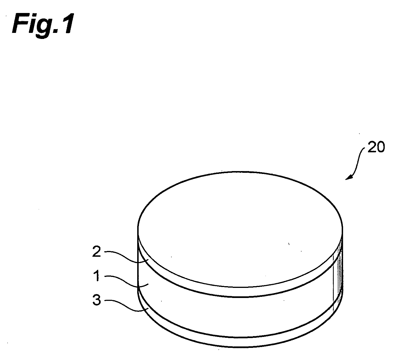
[0095]A piezoelectric element 20 such as shown in FIG. 1 was fabricated by the following procedure. First, sodium carbonate (Na2CO3) powder, potassium carbonate (K2CO3) powder, lithium carbonate (Li2CO3) powder, niobium oxide (Nb2O5) powder, tantalum oxide (Ta2O5) powder, strontium carbonate (SrCO3) powder, zirconium oxide (ZrO2) powder and barium carbonate (BaCO3) powder were prepared. Manganese carbonate (MnCO3) powder was also prepared as the starting material for the accessory component. After thoroughly drying the starting materials, they were weighed out so that the composition (molar ratio) of the complex oxide as the major component of the piezoelectric ceramic conformed to the following formula (9).

0.945(Na0.57K0.38Li0.05)(Nb0.9Ta0.1)O3+0.05SrZrO3+0.005Ba(Nb0.9Ta0.1)2O6  (9)

[0096]The MnCO3 powder was also weighed out to 0.5 mass % in terms of MnO, based on the total complex oxide composition of formula (9) above.

[0097]The strontium carbon...

examples 2-4

[0109]Piezoelectric elements were fabricated and their piezoelectric characteristics evaluated in the same manner as Example 1, except that the MnCO3 powder was added in an amount so that the mass ratio in terms of MnO with respect to the total complex oxide composition of formula (9) above was as listed in Table 1. The evaluation results are shown in Table 1.

example 5

Fabrication of Piezoelectric Element

[0110]A piezoelectric element was fabricated in the same manner as Example 1, except that Cu2O powder was prepared instead of MnCO3 powder, and the Cu2O powder was mixed so that the mass ratio with respect to the total complex oxide composition of formula (9) above was 1.0 mass % in terms of CuO.

[0111]{Observation of Microstructure and Compositional Analysis}

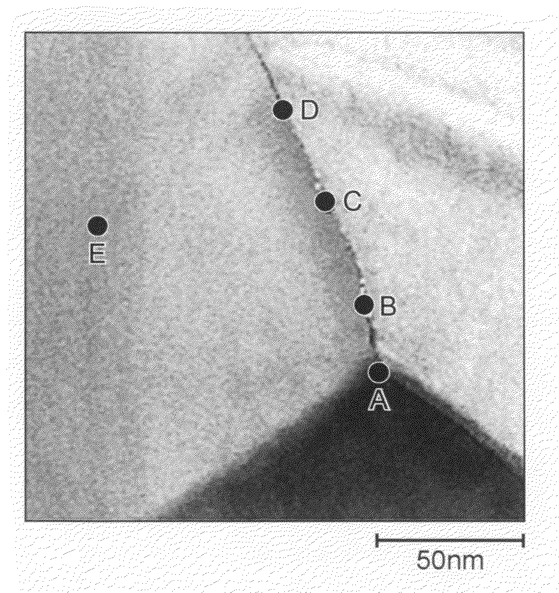
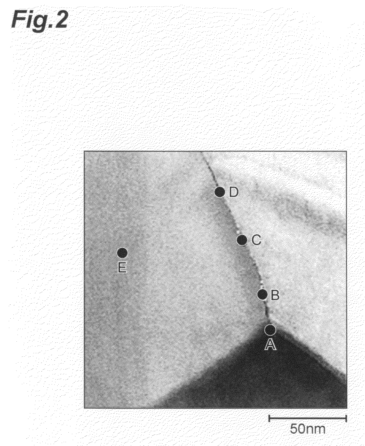
[0112]Observation of the microstructure and compositional analysis of the obtained piezoelectric ceramic were accomplished using an STEM-EDS, in the same manner as Example 1. FIG. 4 is a STEM (Scanning Transmission Electron Microscope) photograph showing the microstructure of the piezoelectric ceramic of Example 5. FIG. 9 is a STEM (Scanning Transmission Electron Microscope) photograph showing an enlarged view of the area near a grain boundary of the piezoelectric ceramic shown in FIG. 4.

[0113]FIG. 10 is a chart showing the results of analysis of different points of the piezoelectric ceramic o...


PUM

PropertyMeasurementUnit
Curie temperaturesaaaaaaaaaa
Curie temperatureaaaaaaaaaa

Abstract

A piezoelectric ceramic 1 in a piezoelectric element 20 contains, as a major component, a composition containing one or more complex oxides with metal elements other than lead as constituent elements. At least one of the complex oxides includes an alkali metal and Nb as constituent elements. Also, either or both of the elements Mn and Cu are segregated at the grain boundaries of the composition.

Description

BACKGROUND OF THE INVENTION[0001]1. Field of the Invention[0002]The present invention relates to a piezoelectric ceramic and to a piezoelectric element employing it.[0003]2. Related Background Art[0004]Known piezoelectric ceramics exhibit piezoelectricity, whereby application of an electric field generates mechanical strain and stress. Such piezoelectric ceramics are used in various types of oscillating element including actuators, and in sounding bodies, sensors and the like.[0005]Actuators employing piezoelectric ceramics characteristically allow high precision to be obtained for fine displacement and produce large generated stress, and they are used for positioning of precision machine tools and optical devices. The piezoelectric ceramics used in actuators are, in most cases, made of lead zirconate titanate (PZT) which has excellent piezoelectric properties. However, because lead zirconate titanate contains a large amount of lead, concerns have been raised in recent years regardi...

Claims


Application Information

Patent Timeline
Patent Type & Authority Applications(United States)
IPC IPC(8): H01L41/187C04B35/00H01L41/083H01L41/22H01L41/39H02N2/00
CPCC04B35/495H01L41/43C04B2235/3201C04B2235/3203C04B2235/3206C04B2235/3208C04B2235/3213C04B2235/3215C04B2235/3236C04B2235/3248C04B2235/3255C04B2235/3262C04B2235/3281C04B2235/768C04B2235/85H01L41/083H01L41/1873C04B35/62695H10N30/50H10N30/8542H10N30/097
Inventor FURUKAWA, MASAHITOTSUKADA, TAKEOTANAKA, DAISUKESAKAMOTO, NORIMASA
Owner TDK CORPARATION
Learn More