Reusable crucibles and method of manufacturing them

a technology of crucibles and crucibles, which is applied in the direction of electrical appliances, climate sustainability, lamination, etc., can solve the problems of cracking and breaking of crucibles when releasing silicon metal, cracking of ingots, and risk of local thermal runaway

Inactive Publication Date: 2009-10-08
REC SCANWAFER
View PDF4 Cites 17 Cited by
  • Summary
  • Abstract
  • Description
  • Claims
  • Application Information

AI Technical Summary

Benefits of technology

[0043]The crucibles according to the invention may advantageously be equipped with a tapering in order to ease the release of the ingot. The crucible can optionally be coated with some material to ease the release of the ingot after casting.
[0053]The production of the crucible made from a plate will be easier and more economical due to a lower failure rate in the casting step and a higher density of material in the furnace and the possibility for higher reaction rates during nitriding.

Problems solved by technology

During cooling of the ingot, the strong adherence leads to cracking of the ingot due to build-up of mechanical tension resulting from the higher coefficient of thermal expansion of the silicon as compared to silica.
This gives a significant contribution to the production costs of the ingots.
There was however a problem with wetting by the liquid silicon and consequently a strong adherence between the ingot and crucible, leading to cracking and breakage of the crucibles when releasing the silicon metal.
The strongly exothermic reaction causes problems in that hot areas in the charge will tend to react faster than surrounding material, leading to a risk of local thermal runaway.
If thermal runaway occurs, there is a high probability of cracks and flaws in the material.
The problem with thermal runaway sets practical limits to the physical dimensions of the objects that are to be formed, since the objects should have relatively thin bulk phases (high aspect ratios and thin walls) in order to allow a sufficient heat transport from the reaction zone during nitriding.
The RBSN-process is therefore not suited for producing crucibles for industrial scale production of semiconductor silicon, such as for instance in present day direct solidification furnaces (DS-furnaces) which forms ingots of sizes up to 100×100×40 cm3 or more.

Method used


Image

  • Reusable crucibles and method of manufacturing them
  • Reusable crucibles and method of manufacturing them
  • Reusable crucibles and method of manufacturing them

Examples


example of an embodiment

OF THE INVENTION

[0057]The invention will be described in further detail by way of examples of embodiments of the invention according to the second or fourth aspect of the invention, production of plate elements that assembled to form a square cross-sectional reusable crucibles. These examples should by no means be considered to represent a limitation of the general inventive concept of forming reusable crucibles of nitride bonded silicon nitride, NBSN, any conceivable shape and dimensions of NBSN elements, in one piece or assembles by several pieces, that may function as crucible for solidifying silicon may be employed.

[0058]The plate elements in the crucible according to example 1 and 2 are all made by casting a slurry of >60 weight % silicon nitride particles and <40 weight % Si particles into a mould, preferably made from plaster with the net shape of plate element that is to be formed, including grooves and apertures in order to obtain plates suitable for assembly into crucibles...

example 1

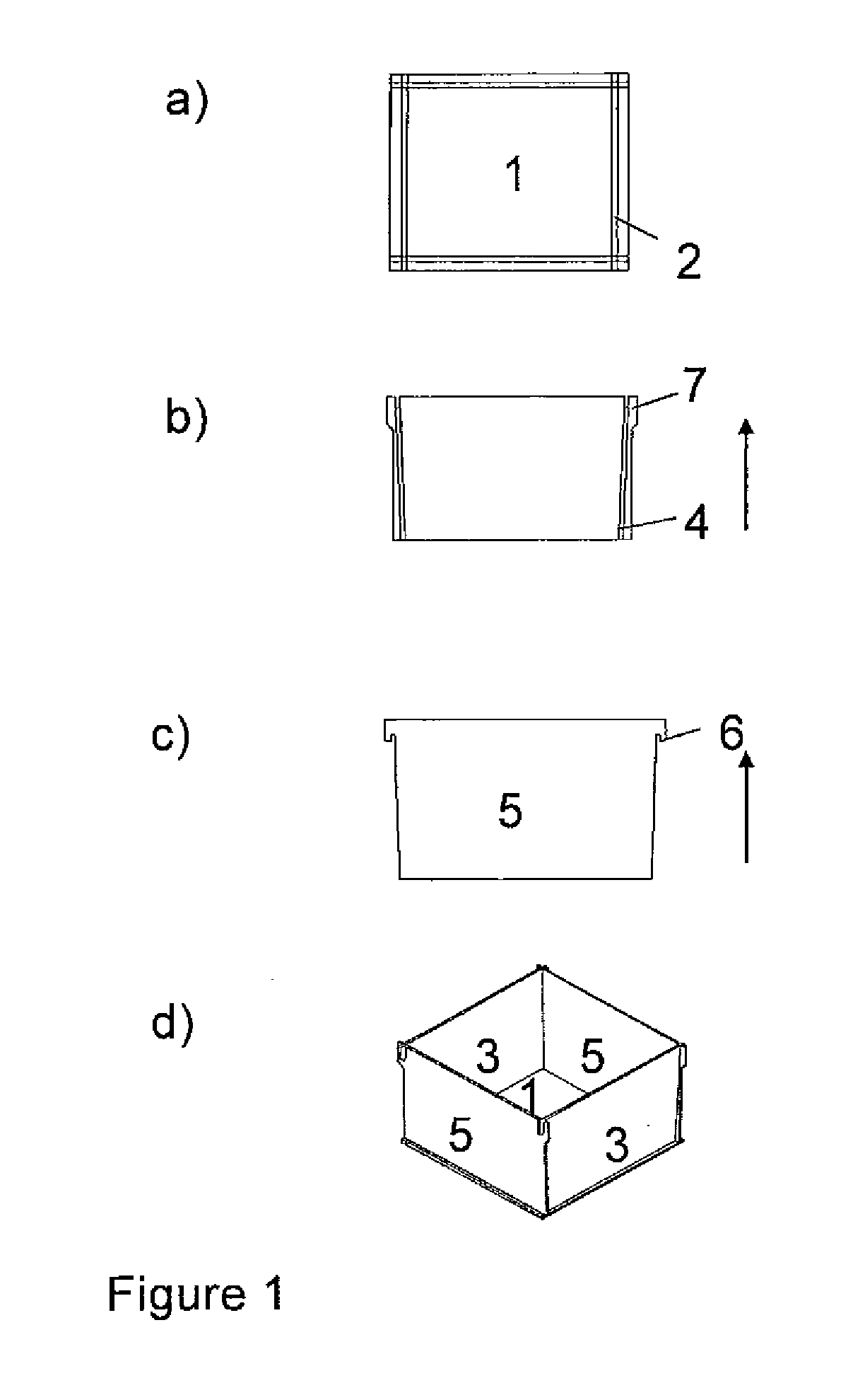
[0060]FIG. 1 is a schematic view of the plate elements forming the bottom and side-walls of a square cross-sectional crucible according to a first example of the invention. All elements are made of NBSN. The figure also shows the assembled crucible.

[0061]FIG. 1a illustrates the bottom plate 1, which is a quadratic plate with a groove 2 on the upward facing surface along each of its sides. The grove is fitted to the thickness of the side elements forming the walls of the crucible such that the lower edge of the side walls enters into the groove and forms a tight fit. Alternatively, the side elements and the bottom groove may be given a complementary shape such as e.g. a plough and tongue.

[0062]FIG. 1b shows one rectangular wall element 3. There will be used two of these at opposing sides, see FIG. 1d. The side element 3 is equipped with a groove 4 along both edges on the surface facing inwards into the crucible. The grooves 4 are dimensioned to give a tight fit with the side edges of...

example 2

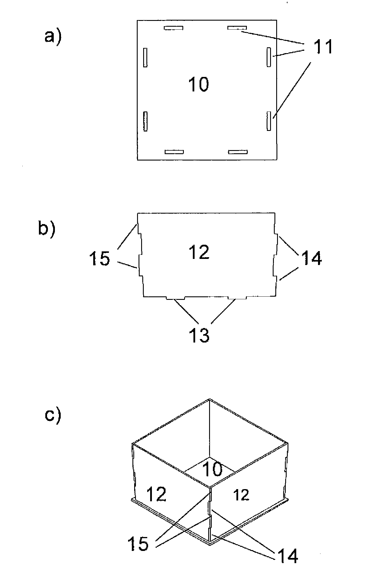
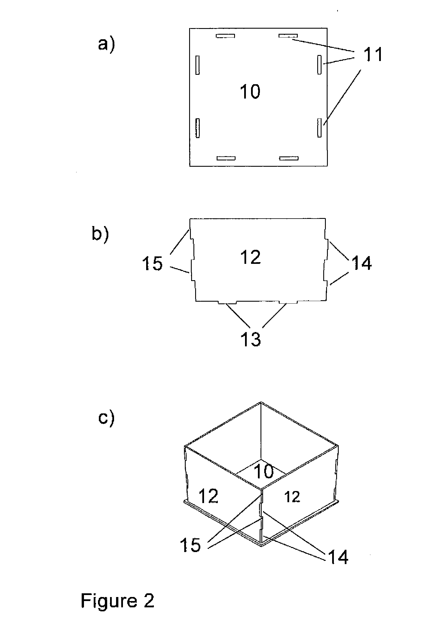
[0065]FIG. 2 is a schematic view of the plate elements forming the bottom and side-walls of a square cross-sectional crucible according to a second example of the invention. All elements are made of NBSN. The figure also shows the assembled crucible.

[0066]FIG. 2a illustrates the bottom plate 10, which is a quadratic plate with two elongated apertures 11 along each of its sides. The dimensions of the apertures are fitted such that they can receive a downward facing protrusion of the side walls and form a tight fit. It is also envisioned to include grooves (not shown) running aligned with the centre axis of the apertures 11, similar to the grooves 2 of the bottom plate 1 of the first example.

[0067]FIG. 2b shows one wall element 12. There will be four of these elements, see FIG. 2c. The side element 12 is equipped with two protrusions 14, 15 on each side and two downward protrusions 13. The side protrusions are dimensioned such that the protrusions 14 enter the space between the protru...


PUM

PropertyMeasurementUnit
temperatureaaaaaaaaaa
temperaturesaaaaaaaaaa
outer diameteraaaaaaaaaa

Abstract

This invention relates to reusable crucibles for production of ingots of semiconductor grade silicon made of nitride bonded silicon nitride (NBSN). The crucibles may be made by mixing silicon nitride powder with silicon powder, forming a green body of the crucible, and then heating the green body in an atmosphere containing nitrogen such that the silicon powder is nitrided forming the NBSN-crucible. Alternatively the crucibles may assembled by plate elements of NBSN-material that are to be the bottom and walls of a square cross-section crucible, and optionally sealing the joints by applying a paste comprising silicon powder and optionally silicon nitride particles, followed by a second heat treatment in a nitrogen atmosphere.

Description

[0001]This invention relates to reusable crucibles for production of ingots of semiconductor grade silicon, including solar grade silicon, and to a method for manufacturing the reusable crucibles.BACKGROUND[0002]The world supplies of fossil oil are expected to be gradually exhausted in the following decades. This means that our main energy source for the last century will have to be replaced within a few decades, both to cover the present energy consumption and the coming increase in the global energy demand.[0003]In addition, many concerns are raised that the use of fossil energy increases the earth greenhouse effect to an extent that may turn dangerous. Thus the present consumption of fossil fuels should preferably be replaced by energy sources / carriers that are renewable and sustainable for our climate and environment.[0004]One such energy source is solar light, which irradiates the earth with vastly more energy than the present day consumption, including any foreseeable increase...

Claims


Application Information

Patent Timeline
Patent Type & Authority Applications(United States)
IPC IPC(8): C30B19/00B29D31/00C01B21/068B29D99/00
CPCC30B11/002C30B29/06Y10T117/1092H01L31/1804C30B35/002C04B35/591C04B37/005C04B2235/3873C04B2235/428C04B2235/46C04B2235/94C04B2235/945C04B2237/08C04B2237/16C04B2237/368Y02P70/50C04B35/584C30B13/14C30B15/10
Inventor ROLIGHETEN, RUNERIAN, GJERTRUDJULSRUD, STEIN
Owner REC SCANWAFER
Why Eureka
Try Eureka