Thin film transistor and method for manufacturing the same
- Summary
- Abstract
- Description
- Claims
- Application Information
AI Technical Summary
Benefits of technology
Problems solved by technology
Method used
Image
Examples
embodiment 1
[0047]In this embodiment, an example of a mode of a thin film transistor will be described with reference to the drawings.
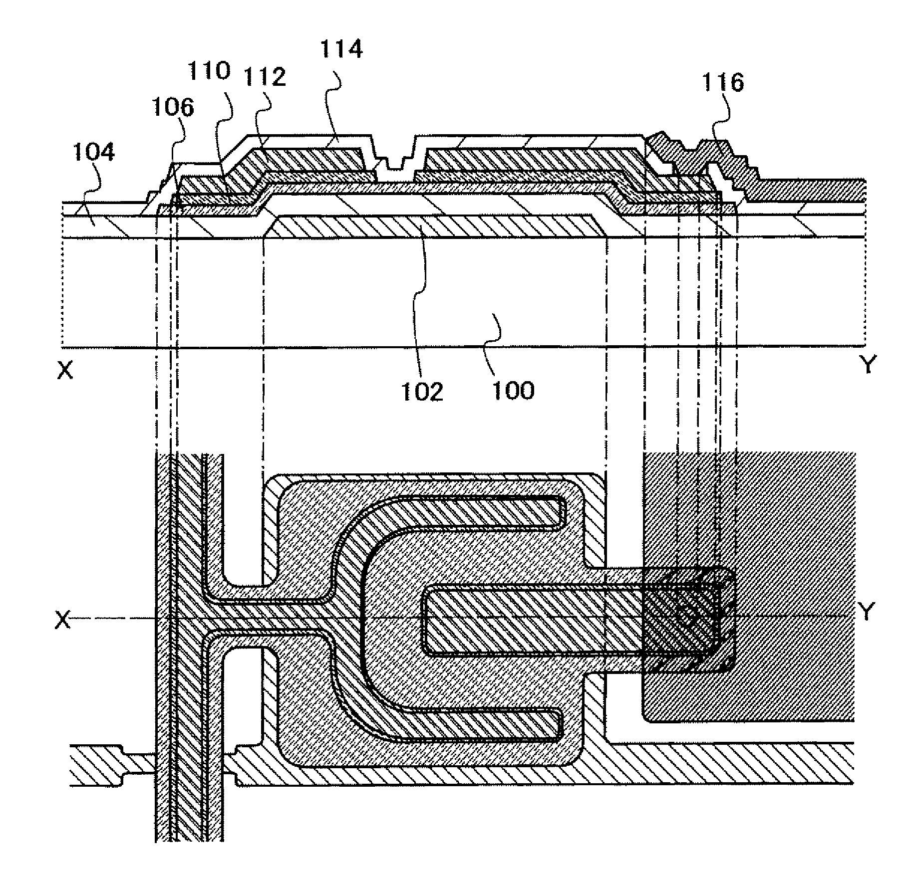
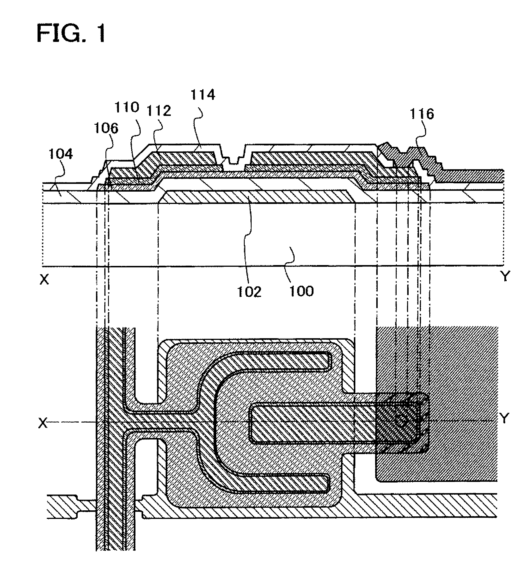
[0048]FIG. 1 is a top view and a cross-sectional view of a thin film transistor according to this embodiment. The thin film transistor illustrated in FIG. 1 includes a gate electrode layer 102 over a substrate 100; a gate insulating layer 104 covering the gate electrode layer 102; a semiconductor layer 106 provided over and in contact with the gate insulating layer; and source and drain regions 110 provided over and in contact with the semiconductor layer 106. Further, the thin film transistor includes wiring layers 112 provided over and in contact with the source and drain regions 110. The wiring layers 112 form source and drain electrodes. The thin film transistor includes, over the wiring layers 112, an insulating layer 114 serving as a protective film. Each layer is patterned into a desired shape.
[0049]Note that the thin film transistor illustrated in FIG. 1 ...
embodiment 2
[0131]In this embodiment, a method for manufacturing the thin film transistor illustrated in FIG. 1, which is different from the method described in Embodiment 1, will be described. In this embodiment, as in Embodiment 1, a semiconductor layer including inverted conical or inverted pyramidal crystal particles is formed. However, a method in which nitrogen is included in the semiconductor layer is different from that described in Embodiment 1.
[0132]In this embodiment, the gate insulating layer which is in contact with the semiconductor layer is formed using silicon nitride, whereby the concentration of nitrogen in the semiconductor layer is controlled, and the semiconductor layer including inverted conical or inverted pyramidal crystal particles is formed. A series of steps from a step of forming the gate insulating layer 104 to a step of forming the semiconductor layer 109 including an impurity element which serves as a donor will be described hereinafter with reference to FIG. 9.
[0...
embodiment 3
[0141]In this embodiment, a manufacturing method of the thin film transistor illustrated in FIG. 1, which is different from those of Embodiments 1 and 2, will be described. In this embodiment, as in Embodiments 1 and 2, a semiconductor layer including inverted conical or inverted pyramidal crystal particles is formed. However, a method in which nitrogen is contained in the semiconductor layer is different from those described in Embodiments 1 and 2.
[0142]In this embodiment, the treatment chamber 141 is cleaned before formation of the semiconductor layer and after that the inner wall of the chamber is covered with a silicon nitride layer, whereby nitrogen is made to be contained in the semiconductor layer, the concentration of oxygen is kept low and the concentration of nitrogen is made higher than the concentration of oxygen. A series of steps from a step of forming the gate insulating layer 104 to a step of forming the semiconductor layer 109 including an impurity element which ser...
PUM
| Property | Measurement | Unit |
|---|---|---|
| Carrier concentration | aaaaa | aaaaa |
| Carrier concentration | aaaaa | aaaaa |
| Carrier concentration | aaaaa | aaaaa |
Abstract
Description
Claims
Application Information
 - R&D
- Intellectual Property
- Life Sciences
- Materials
- Tech Scout
- Unparalleled Data Quality
- Higher Quality Content
- 60% Fewer Hallucinations
Browse by: Latest US Patents, China's latest patents, Technical Efficacy Thesaurus, Application Domain, Technology Topic, Popular Technical Reports.
© 2025 PatSnap. All rights reserved.Legal|Privacy policy|Modern Slavery Act Transparency Statement|Sitemap|About US| Contact US: help@patsnap.com


