Sputter target, method for manufacturing a layer, particularly a tco (transparent conductive oxide) layer, and method for manufacturing a thin layer solar cell

a technology of transparent conductive oxide and sputter target, which is applied in the direction of electrolysis components, vacuum evaporation coatings, coatings, etc., can solve the problems of inability to avoid “target poisoning” and instabilities of the process, and achieve low oxygen bombardment, high sputter rate, and stable coating

Inactive Publication Date: 2009-11-05
APPLIED MATERIALS INC
View PDF3 Cites 11 Cited by
  • Summary
  • Abstract
  • Description
  • Claims
  • Application Information

AI Technical Summary

Benefits of technology

[0008]It is an object of the present invention to provide a sputter target and a method for manufacturing a layer, particularly a TCO (transparent conductive oxide) layer, as well as a method for manufacturing a thin layer solar cell, wherein the amount / rate of oxygen deposited in the coating film may be controlled while maintaining a high sputter rate, low oxygen bombardment of the deposited film and a stable coating process.

Problems solved by technology

However, it can not be avoided that reactions of the reactive gas also occur on the surface of sputter target causing “target poisoning”.
Thus in reactive oxidic sputter processes of metallic targets instabilities of the process may be caused.
For example, poisoning of the sputter target reduces the thin film growth rate, thus reducing the use of reactive gas, and thus resulting in even more target poisoning.
A further negative effect of reactive sputtering in an oxidic atmosphere is that the substrate is bombarded with negatively charged oxygen ions generated on the surface of the target, particularly at low deposition rates.
However, the bombardment with oxygen ions deteriorates the etchability of the ZnO:Al layer.
Furthermore, it is difficult to control or vary the oxygen content obtained in the deposited ZnO film.

Method used


Image

  • Sputter target, method for manufacturing a layer, particularly a tco (transparent conductive oxide) layer, and method for manufacturing a thin layer solar cell
  • Sputter target, method for manufacturing a layer, particularly a tco (transparent conductive oxide) layer, and method for manufacturing a thin layer solar cell
  • Sputter target, method for manufacturing a layer, particularly a tco (transparent conductive oxide) layer, and method for manufacturing a thin layer solar cell

Examples


Embodiment Construction

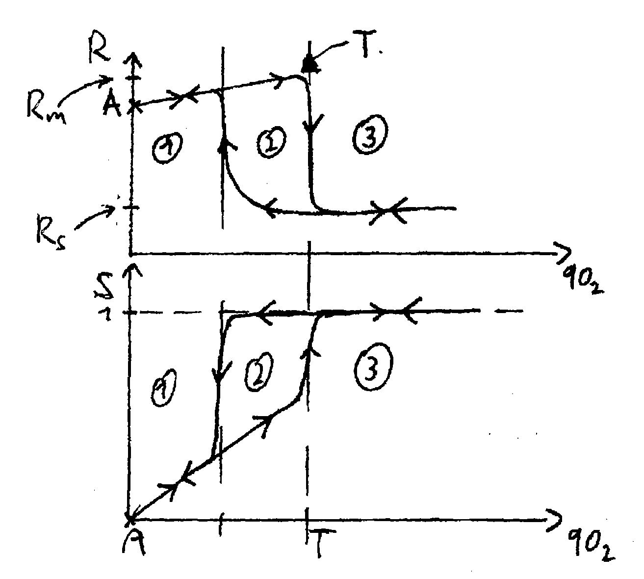
[0040]FIGS. 1a and 1b illustrate the hysteresis and the stoichiometric proportion, respectively, depending on the O2 flow when depositing a ZnO film from a metallic target in a reactive sputter process.

[0041]In FIG. 1a the deposition rate R is indicated responsive to the oxygen flow. When increasing the oxygen flow from a starting point A in an area of oxygen flow indicated with (1) and (2) (first branch of the hysteresis loop) the maximum deposition rate R is reached immediately before reaching an instable transition point T. When further increasing the oxygen flow into an area of oxygen flow indicated with (3), the deposition rate R decreases rapidly to a more or less stable value R,. At this point, the deposition rate is quite low while the process is stable over a wide range. Even when decreasing the oxygen flow into the area of oxygen flow indicated with (2) the deposition rate does not vary considerably (second branch of the hysteresis loop). Only when approaching the area of ...


PUM

PropertyMeasurementUnit
Transparent Conductiveaaaaaaaaaa
hysteresisaaaaaaaaaa
deposition rateaaaaaaaaaa

Abstract

In the present invention a sub-stoichiometric ceramic ZnOx:Al target, with 0.3<x<1, is used for depositing a ZnO:Al layer in a reactive sputtering process. The process is carried out in an Ar/O2 atmosphere. The diagram depicts the deposition rate R depending on the oxygen flow in a sputtering process according to the present invention compared with a conventional sputter process using a stoichiometric ZnO target. The upper line x<1 indicates the deposition rate R when using the inventive target and process. The lower line x=1, for comparison only, indicates the deposition rate R when using a stoichiometric ceramic ZnO target. It can be seen from the diagram that both processes are quite stable as there are no steep slopes when varying the oxygen flow. However, the line x<1 is above the line x=1. Therefore, a working point P may be selected which has a higher deposition rate R than a corresponding working point P of a corresponding ceramic target. A higher deposition rate, however, entails a lower bombardment of the deposited layer with oxygen ions. Therefore, the quality of the ZnO:Al layer is improved as far as the conductivity and the etchability of the layer are concerned.

Description

FIELD OF THE INVENTION[0001]The present invention relates to a sputter target for the use in a reactive sputtering process for depositing a layer on a substrate, comprising at least a first metal element Me1 of the periodic table, and a quantity of oxygen. Furthermore, the invention relates to a method for manufacturing a layer on a substrate, particularly a TCO (Transparent Conductive Oxide) layer, including providing an above-mentioned sputter target in a process chamber. The invention also relates to a method for manufacturing a thin layer solar cell, comprising the step of: a) depositing a layer on a substrate using a method mentioned above.DESCRIPTION OF THE PRIOR ART[0002]Sputter coating is a well-known method for depositing thin films of different materials on a substrate. Sputter processes include eroding material from a target which is then deposited on a substrate. Sputtering processes are often used to deposit metal thin films on a substrate in an inert gas atmosphere, e....

Claims


Application Information

Patent Timeline
Patent Type & Authority Applications(United States)
IPC IPC(8): C23C14/00
CPCC23C14/3414C23C14/086
Inventor MUELLER, JOACHIMSEVERIN, DANIELKRESS, MARKUS
Owner APPLIED MATERIALS INC
Why Eureka
Try Eureka