Powdered fuel conversion systems and methods

a technology of powdered fuel and conversion systems, applied in the direction of combustion types, combustion of lump and pulverulent fuel, combustion types, etc., can solve the problems of increasing the cost of fuel storage, etc., to achieve the effect of improving stability

Active Publication Date: 2009-11-05
MCKNIGHT JAMES K +2
View PDF29 Cites 48 Cited by
  • Summary
  • Abstract
  • Description
  • Claims
  • Application Information

AI Technical Summary

Benefits of technology

[0053]A burner system of the present invention operates based on the fluid mechanics driven process of a moving stream of a powdered fuel in an oxidizing gas, feeding a stable stationary deflagrating flame wave with on-off control. Balancing mass flow velocity of an explosible fuel dispersion with deflagrating flame front wave velocity produces a stationary and stable combustion front a

Problems solved by technology

Second, using technology formerly only affordable in power plant furnace systems, these smaller furnaces and boilers are beginning to experience technology additions to reduce airborne post combustion pollutants, since it has not been cost-effective on a per BTU basis or mandated outside the power plant.
Ultra-clean coal, may soon become an affordable option for the residential and commercial users, but due to processing costs, has yet to become economically attractive for large coal fired generating stations.
The use of biomass for heating or transportation is often limited by our experiences as well, both on individual and governmental levels.
For example, a high percent volatiles can cause heating value loss or excess smoking issues for stoker-fired plants, if the specific furnace has inadequate space and time to mix the volatile gases with air and completely combust them.
As a result, carbon loss will be high unless pulverization is very fine.
By relying on the % volatiles consumed in multi-phase combustion combined with large reactor size and residence time common to all furnaces, it is clear that there is no teaching in the art for using only substantially explosible coal powder as a feed

Method used


Image

  • Powdered fuel conversion systems and methods
  • Powdered fuel conversion systems and methods
  • Powdered fuel conversion systems and methods

Examples


Embodiment Construction

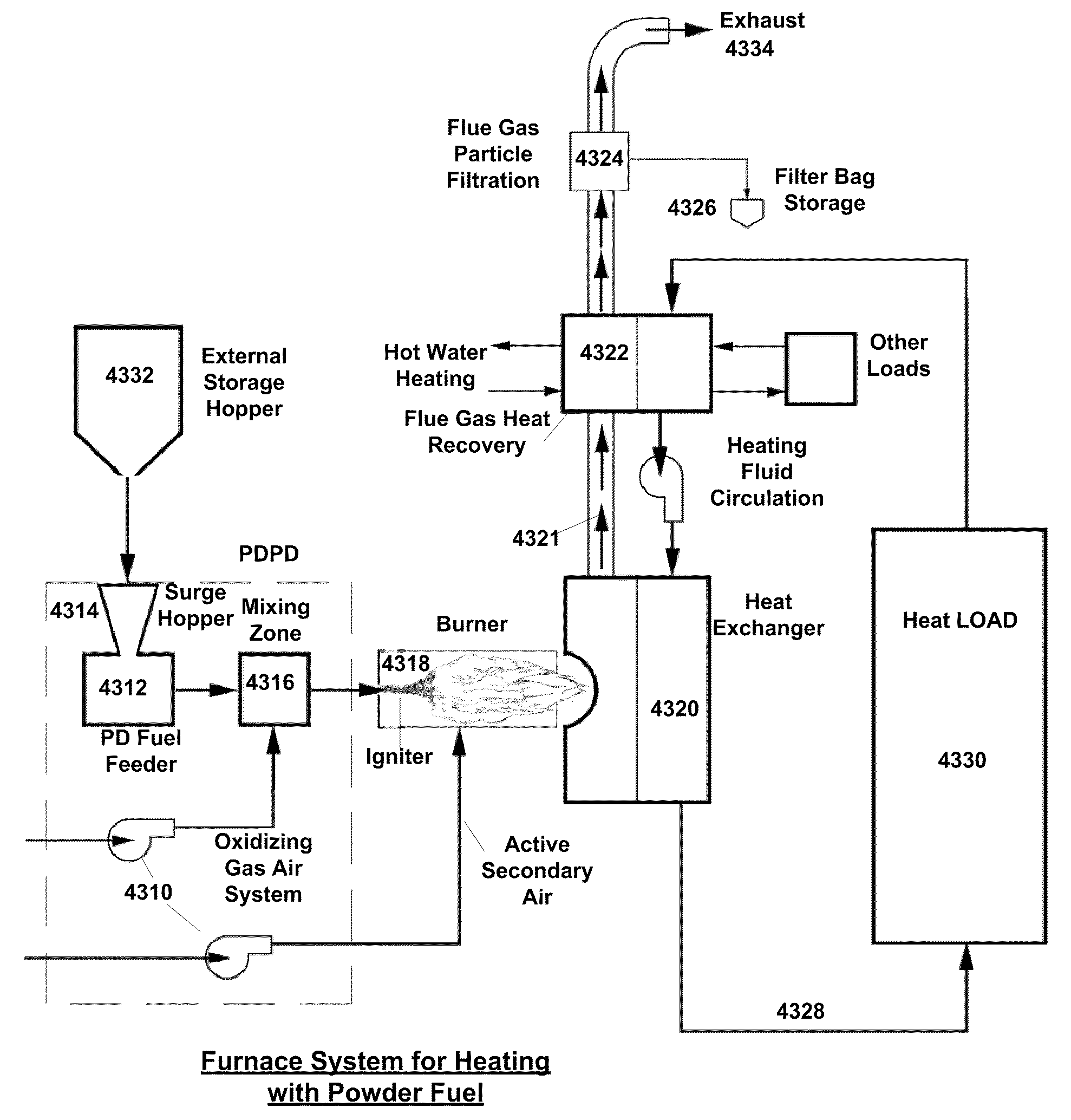
[0120]The invention described herein enables the sustained combustion of explosible powder mixed with an oxidizing gas in a dispersed travelling suspension to produce heat or perform work. The combustion technology and systems disclosed herein provide an opportunity for a major reduction in dependence on fossil fuels, leveraging and utilizing local production and distribution of renewable biomass energy fuel to fill in this gap, without the introduction of significant quantities of “new” CO2 into the atmosphere.

[0121]No burner system to our knowledge is designed to exclusively handle explosible biomass and other solid fuels suspended in a substantially explosible mixture of an explosible powder with an oxidizing gas, preferably air, with the result of direct energy conversion, in a manner that mimics single-phase combustion of propane or methane gas.

[0122]We are the first to develop, use, and disclose an explosible powder as a fuel in a burner, where the burner was designed around c...


PUM


Abstract

The burner preferably exclusively burns substantially explosible solid fuels and preferably has instant ON-OFF thermostat control, wastes no energy preheating the enclosure or external air supply, achieves stable combustion the moment the powder-air mix is ignited in our burner, is used in the upward vertical mode except for oil burner retrofits, burns a solid fuel in a single-phase regime as if it were a vaporized liquid or gas, is designed to complete combustion within the burner housing itself rather than in a large, high temperature furnace enclosure which it feeds, has an ultra-short residence time requirement, is a recycle consuming burner with self-contained management of initially unburned particles, is much smaller, simpler and lower cost, has a wider dynamic range/turndown ratio, is more efficient in combustion completeness and thermal efficiency, and operates with air-fuel mix approximately at the flame speed.

Description

REFERENCE TO RELATED APPLICATIONS[0001]This application claims one or more inventions which were disclosed in U.S. Provisional Application No. 61 / 042,996, filed Apr. 7, 2008, entitled “POWDERED FUEL CONVERSION SYSTEMS AND METHODS” and U.S. Provisional Application No. 61 / 074,244, filed Jun. 20, 2008, entitled “POWDERED FUEL CONVERSION SYSTEMS AND METHODS”. The benefit under 35 USC § 119(e) of the United States provisional applications is hereby claimed, and the aforementioned applications are hereby incorporated herein by reference.[0002]This is a continuation-in-part patent application of co-pending PCT Patent Application No. PCT / US2007 / 024044, entitled “POWDERED FUELS, DISPERSIONS THEREOF, AND COMBUSTION DEVICES RELATED THERETO”, filed Nov. 16, 2007, which claims priority to U.S. Provisional Application No. 60 / 859,779, filed Nov. 17, 2006, U.S. Provisional Application No. 60 / 868,408, filed Dec. 4, 2006, and U.S. Provisional Application No. 60 / 993,221, filed Sep. 10, 2007. The above...

Claims


Application Information

Patent Timeline
IPC IPC(8): F23N5/00F23B30/02F23D1/00F23D1/02F23K3/00F23N1/02
CPCF23C6/045Y02E50/30F23G5/033F23G5/444F23G5/46F23G5/50F23G7/10F23G2202/106F23G2205/20F23G2206/203F23G2207/101F23G2207/102F23G2207/104F23G2207/112F23G2207/113F23G2207/20F23G2207/30Y02E20/12Y02E50/10F23C2900/06041F23C1/12F23C6/02F23D1/005F23D1/02F23G2203/00F23N1/02F23N5/00
Inventor MCKNIGHT, JAMES K.BACORN, EDWARDWHITE, KEN W.
Owner MCKNIGHT JAMES K
Why Eureka
Try Eureka