[0011]In this case, the fabric used according to the invention allows numerous possible configurations to achieve these advantageous effects. On the one hand, the fabric is preferably formed from electrically non-conducting or weakly conducting fibres to which a suitably conducting
coating is then applied, before or after the weaving, wherein according to a further development it is favourable to use carbon or (conducting)
polymer fibres. On the other hand, suitable
copper, titanium or
aluminium fibres, for example, are used for conducting fibres.
[0012]According to a further development, the conducting layer applied to the fabric to achieve the support substrate (primarily in the case of non-conducting / weakly conducting fibres) can itself again be a (for example, suitably doped) metal oxide, a metal or a conducting
polymer.
[0013]It is also particularly suitable to use the fabric itself to guide the lines required for supplying or leading off the charges to corresponding connecting electrodes of the solar cell; according to a preferred further development of the invention, this is achieved by weaving in these leads in the form of metal wires (which traditionally must be formed at some expense on the conducting glass plates of known solar cells) with the other fibres during the fabrication of the fabric within the scope of the further development according to the invention. In this way, in addition to favourable mechanical flexibility and connecting properties, favourable electrical contacting is also ensured (again with positive effects on the efficiency by reducing ohmic junction resistances).
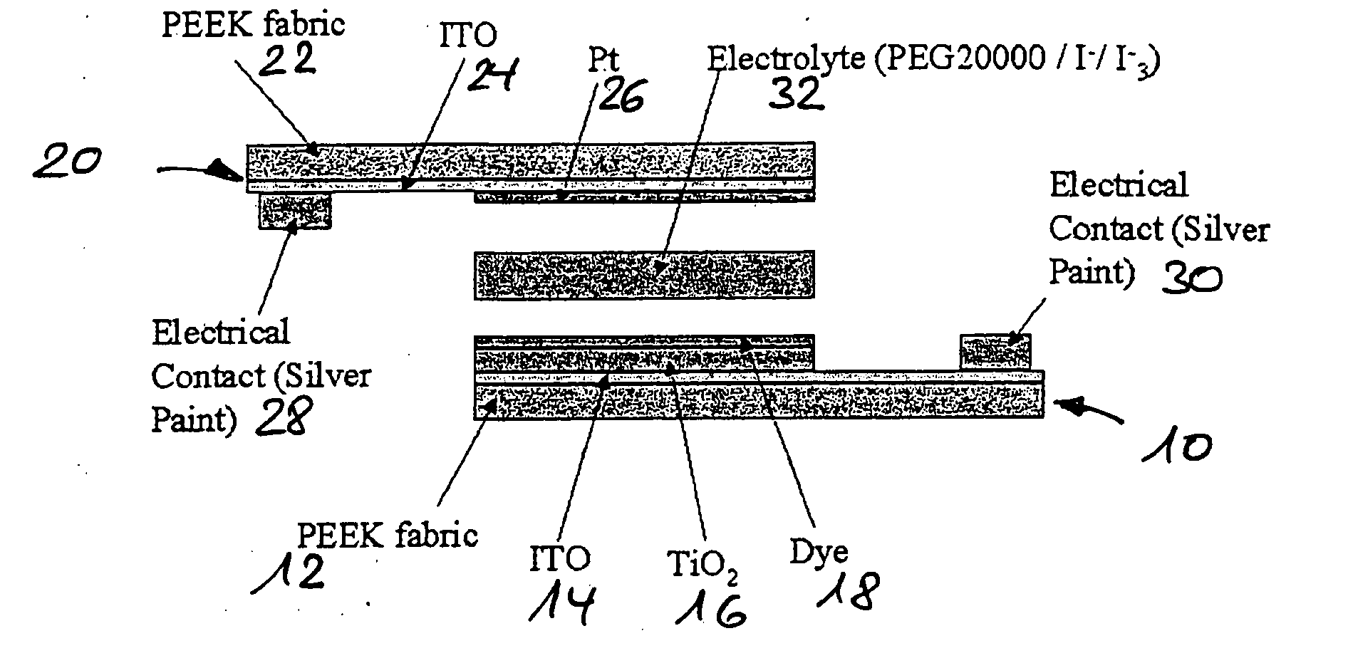
[0014]As has already been described, within the scope of preferred embodiments of the invention, preferably nanostructured TiO2 or ZnO (as examples) are used as metal oxide-semiconductor material since the optimisation between
mechanical stability and elasticity with desired
effective surface area described above can be achieved. Within the scope of preferred further developments of the invention with regard to process technology, this material is additionally dispersed in suitable solvents, applied to the fabric by impregnating and pressed after
drying (volatilising the
solvent). Other suitable methods which form a favourable join with the fabric without disadvantageously impairing this are possibly
sintering, so-called
sol-gel methods or
sputtering.
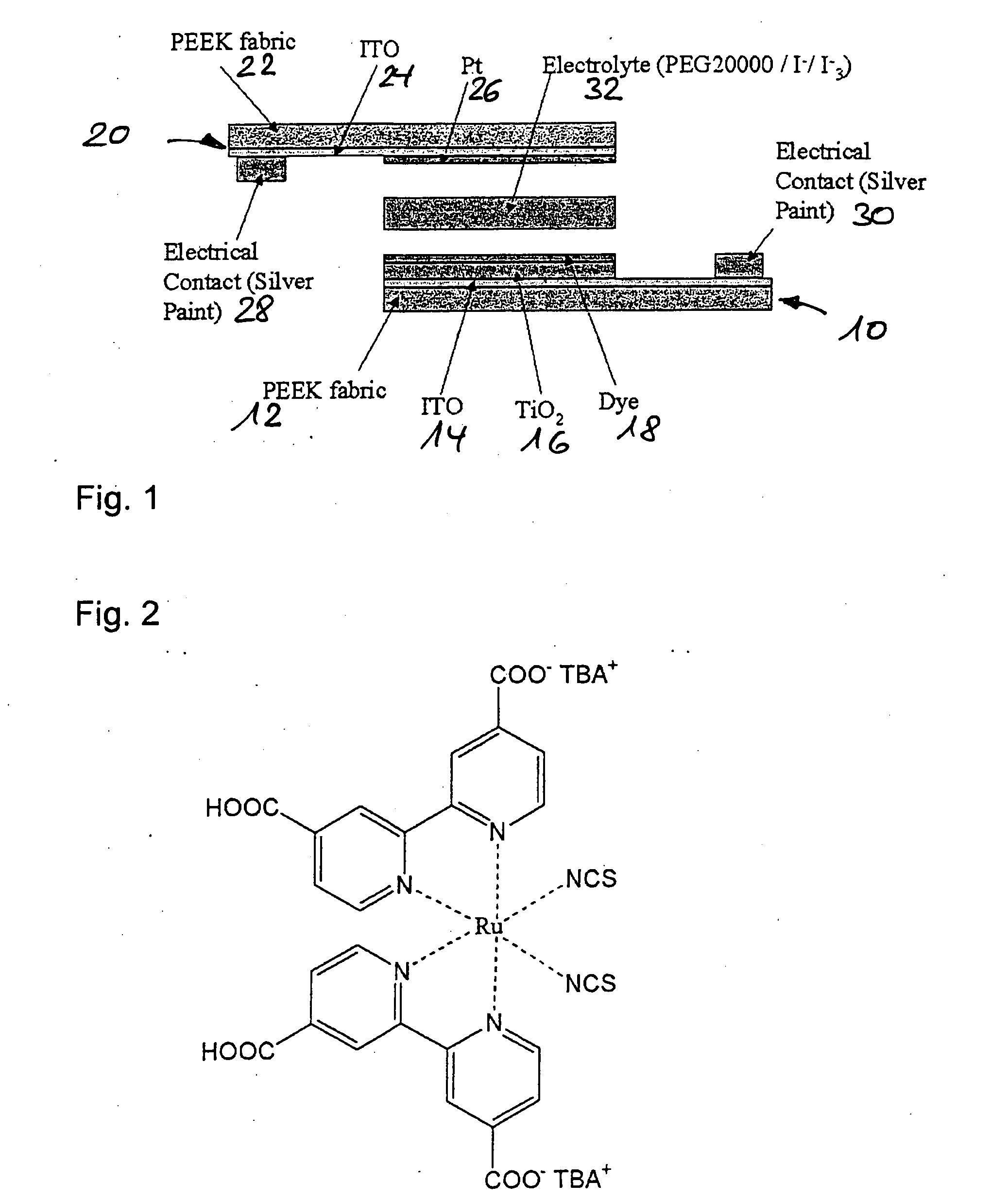
[0015]Then within the scope of the invention, a thin dye layer, according to a further development, monomolecular, i.e., merely having the
layer thickness of a
dye molecule, is applied to the thus provided composite of (conducting) fabric-based fabric substrate with metal oxide-semiconductor layer, again by means of a suitable solution. Both Ru-based metal complexes and also organic dyes are suitable within the scope of the invention wherein, within the scope of selecting the dye layer, it is provided according to the invention that the energy levels of the dye, the semiconductor and the electrolyte are matched to one another, so that the desired photochemical and electrical processes can proceed in an optimised manner.
[0016]A further preferred embodiment of the present invention (best mode) provides that the electrolyte layer according to the invention (possibly by using an
acrylate resin or another deformable and hardenable polymer) in a liquid or fluid state allows the deformation of the cells according to the invention into an approximately arbitrary, desired shape (in particular for
adaptation to a provided usage environment, e.g. in the construction or building sector), whereupon this material can then be hardened and the shaping thereby permanently fixed in its configuration. For this purpose, the electrolyte layer suitably comprises a
solvent, a
redox pair and well as optionally additives which, in the manner possibly of the design with glass-fibre-reinforced plastics, can allow mechanically very stable units, and at the same time achieve the photochemical or photoelectric properties of a DNSC solar cell. Within the scope of suitable further developments of the invention, it is particularly provided that in addition to a suitable curability of the electrolyte provided with corresponding properties (in addition to thermally curing resin,
UV curing resin also particularly comes into consideration here), such curing or permanent deformation is ensured by resins outside the electrolyte (which are therefore not connected to the electrolyte) acquiring such functionality, possibly by an additional outer resin layer which is then, in the manner according to this further development, brought into its permanent form by suitable formulation and the electrolyte material can be selected independently thereof.

