Field emission device and method for fabricating cathode emitter and zinc oxide anode

Inactive Publication Date: 2009-12-17
NATIONAL DEFENSE UNIVERSITY
View PDF5 Cites 26 Cited by
  • Summary
  • Abstract
  • Description
  • Claims
  • Application Information

AI Technical Summary

Benefits of technology

[0016]The object of the present invention is to provide a field emission device and a method for manufacturing a cathode emitter and a zinc oxide anode, which improve the adhesion between the substrate and the emitters, promote illuminating efficiency of zinc oxide film, and satisfy the demands of low costs, simple procedures, large-scaled, mass production, and increasing the lifespan of field emission sources.
[0018]In the above-mentioned method, the substrate can be surface-treated, such as degreased or roughened, preliminarily to improve both surface cleanness and roughness before the substrate is immersed in the zinc solution.
[0025]In conclusion, the principle for manufacturing the cathode emitters made of the zinc oxide / carbon nanomaterial composite in the present invention is as follows. Since the conductive film of zinc oxide becomes sol-gel when film formation, it has good adsorption to the surface-modified carbon nanomaterials having negative charge. After the surface-modified carbon nanomaterials (evenly dispersed) are adsorbed onto the zinc oxide film, the film having pore arrays can transform into a compact film by dehydration under baking at a high temperature. According to this principle, while the zinc oxide film transforms from sol-gel into solid, one end of the surface-modified carbon nanomaterials adsorbed in the pores is embedded into the zinc oxide film owing to film fixation, and then the obtained cathode emitters made of the zinc oxide / carbon nanomaterial composite can have good adhesion and uniformity.
[0027]In the method mentioned above, the substrate can be surface-treated, such as degreased or roughened, preliminarily to improve surface cleanness and roughness before the substrate is immersed in the zinc solution.
[0032]Accordingly, the principle for preparing the anode of zinc oxide phosphor materials in the present invention describes as follows. When the zinc-plating layer is thermal-oxidized with oxygen at a high temperature, zinc is reacted with oxygen to transform into an electroluminescent zinc oxide film. Besides, the ratio of zinc to oxygen in the zinc oxide film can be controlled by different concentrations of oxygen so that phosphor materials having various luminescent properties can be obtained.

Problems solved by technology

However, since the size of such structures is limited to the level of microlithography for forming openings on the substrate and to the vapor deposition for producing metal spikes, the size of light is dramatically restricted.
Besides, the tips of spindt-type field emitters are easily damaged whereby they have a short lifespan.
However, these methods respectively have some problems.
However, the CVD involves complex procedures and expensive equipment in the purpose of depositing CNTs with good field-emission ability.
Furthermore, the deposition temperature is generally higher than the glass transition temperature of the substrate (Tg, about 550° C.) and CNTs have poor adhesion on the glass substrate, short lifespan, and there is difficulty in controlling quality of a single CNT.
Hence, CNTs are only at the stage of research, and rarely applied in the industry.
However, defects such as poor adhesion between CNTs and the substrate, great consumption of CNTs, a need to remove the organic solvent, CNT damage during baking, irregularity of emitters, poor uniformity of luminance etc. are bottlenecks in the screen-printing.
Although this method can improve the defect of CNT inconsistency in the screen-printing and economize on the cost, the adhesion between the CNTs and the substrate is still poor and the thickness of deposited CNTs is not uniform enough.
Although this method can improve the adhesion between the CNTs and the substrate, irregularity of current density occurs easily during electroplating thereby negatively influencing uniformity of the CNTs in the deposited metal, resulting in irregularity of field emitters and poor uniformity of luminance.
However, the electroless plating solution is an unstable system, and its life is short.
If the solution incurs over-high pH value or local overheating, or has some impurities (for example, CNTs) during the electroless plating, some tiny catalytic substances may be produced and this leads to uncontrollable performance of intense autocatalysis in the solution, leading to a decayed solution of the electroless plating.
Among these methods, some are performed at an over-high temperature which limits the substrate materials (such as glass substrate), and some need expensive costs and equipment thereby being unsuitable for large-scaled and mass production.
However, the quality of the zinc oxide film obtained by electroless plating is poorer than that obtained by the others.

Method used


Image

  • Field emission device and method for fabricating cathode emitter and zinc oxide anode
  • Field emission device and method for fabricating cathode emitter and zinc oxide anode
  • Field emission device and method for fabricating cathode emitter and zinc oxide anode

Examples


example 6

Preparation of Cathode Emitters of Zinc Oxide / Carbon Nanomaterial Composite on an ITO Glass Substrate

[0059]An ITO glass substrate is surface-degreased, and then immersed in the zinc electroless plating solution (as shown in Table 4) to form a patterned zinc-plating layer deposited thereon by electroless plating. The substrate is immersed in the chemical conversion coating bath (as shown in Table 1) to oxidize the zinc-plating layer into a zinc oxide film at 30° C. Subsequently, the substrate coated with the zinc oxide film is dipped in a single-walled carbon nanotube aqueous solution, and then it is baked at 200° C. for 5 minutes. The technique of the present example can successfully provide a cathode emitter of zinc oxide / carbon nanomaterial composite having good brightness and uniformity of luminance when a commercial product is used as the anode plate in the field emission device.

[0060]In the present example, the composition of the single-walled carbon nanotube aqueous solution i...

example 7

Preparation of Cathode Emitters of Zinc Oxide / Carbon Nanomaterial Composite on a Metal Plate

[0061]A substrate (an iron plate) is surface-degreased, and then immersed in the zinc electroplating solution (It is obtained from JASCO® Japan, and its commercial name is 9000 Series) to form a patterned zinc-plating layer deposited thereon by electroplating. The substrate is immersed in the chemical conversion coating bath (as shown in Table 1) to oxidize the zinc-plating layer into a zinc oxide film at 40° C. Subsequently, the substrate coated with the zinc oxide film is dipped in a nanodiamond aqueous solution, and then it is baked at 150° C. for 5 minutes. The present example shows that the technique of the present example can successfully provide a cathode emitter of zinc oxide / carbon nanomaterial composite having good brightness and uniformity of luminance.

[0062]In the present example, the composition of the nanodiamond aqueous solution is listed as the following Table 7.

TABLE 7The com...

example 8

Preparation of an Anodic Conductive Phosphor Material of Zinc Oxide, Having High Transmittance, on a Glass Substrate

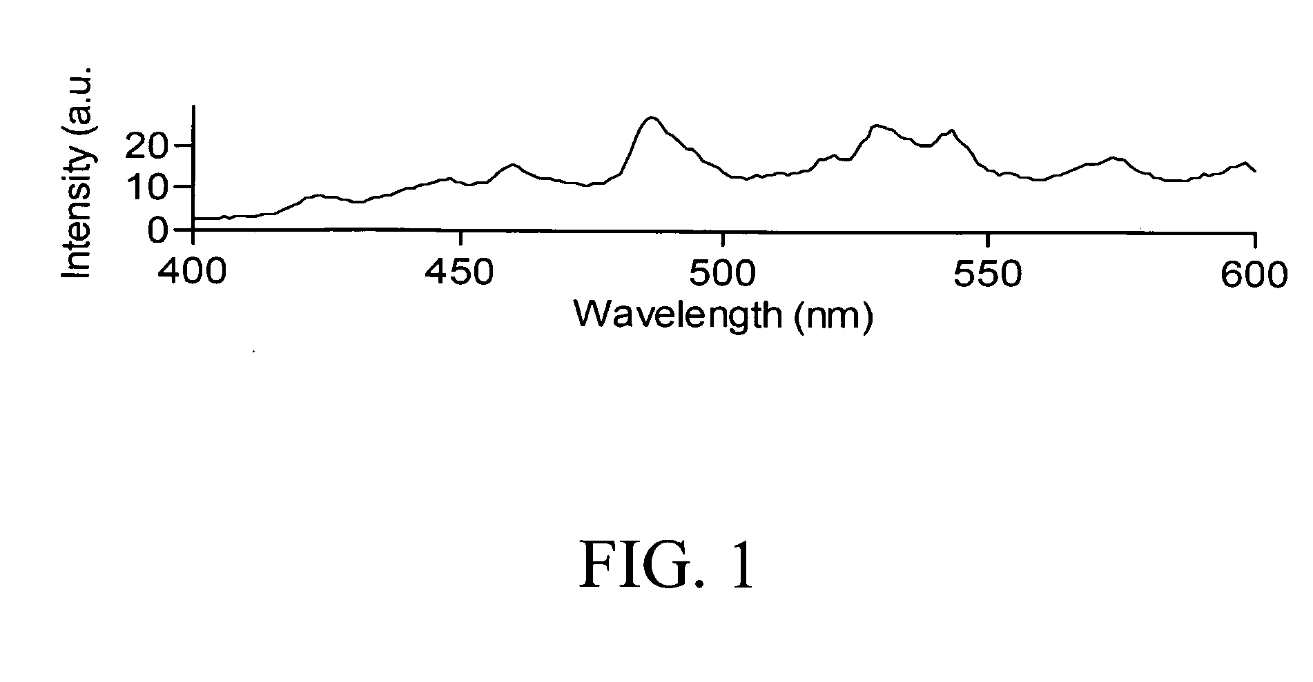
[0063]A glass substrate is surface-degreased and roughened, and then immersed in the zinc electroless plating solution (as shown in Table 4) to form a zinc-plating layer deposited thereon by electroless plating. The substrate is annealed in a muffle furnace at 250° C. under the atmosphere of oxygen at 5 or 100 sccm. Using a photoluminescence spectrometer, it is analyzed that the phosphor material of zinc oxide in the present example can emit blue green luminescence at the wavelength of 470˜510 nm as shown in FIG. 1.


PUM

PropertyMeasurementUnit
Temperatureaaaaaaaaaa

Abstract

The present invention relates to methods for fabricating a cathode emitter and a zinc oxide anode for a field emission device to improve the adhesion between emitters and a substrate and enhance the luminous efficiency of a zinc oxide thin film so that the disclosed methods can be applied in displays and lamps. In comparison to a conventional method for fabricating a field emission device, the method according to the present invention can reduce the cost and time for manufacture and is suitable for fabricating big-sized products. In addition, the present invention further discloses a field emission device comprising a zinc oxide / nano carbon material cathode, a zinc oxide anode and a spacer.

Description

BACKGROUND OF THE INVENTION[0001]1. Field of the Invention[0002]The present invention relates to a field emission device and a method for manufacturing a cathode emitter and a zinc oxide anode and, more particularly, to a field emission device and a method of manufacturing a cathode emitter and a zinc oxide anode for improving the emission intensity and uniformity.[0003]2. Description of Related Art[0004]In 1928, R. H. Fowler and L. W. Nordheim first provided a field emission theory as follows. When a high voltage is applied between two conductors, electrons located on the cathode surface and in the vacuum are of a reduced potential energy while the barrier thickness of the potential energy decreases. In other words, when the voltage is extremely high, potential barrier thickness is small. Therefore, the electrons do not necessarily have potential energy higher than the potential barrier, and they can directly cross the potential barrier, enter the vacuum and be emitted from the cat...

Claims


Application Information

Patent Timeline
IPC IPC(8): H01J1/62C23C22/83
CPCC09K11/54C23C22/47C23C2222/10H01J1/304H01J29/04H01J2329/20H01J31/127H01J63/02H01J2329/0444H01J2329/0455H01J29/20
Inventor CHOU, YU-HSIENSUNG, YUHGER, MING-DERLIU, YIH-MINGKUO, CHUN-WEIYEH, JUN-YUFAN, YUN-CHIH
Owner NATIONAL DEFENSE UNIVERSITY
Why Eureka
Try Eureka