Rare earth magnet and production process thereof

a technology production processes, applied in the field of rare earth magnets, can solve the problems of reducing remanence, affecting the stability of magnetic domains, and conventional techniques, and achieve the effects of preventing coarsening, reducing remanence, and suppressing the substitution of elements rh

Inactive Publication Date: 2010-01-07
DAIDO STEEL CO LTD
View PDF6 Cites 48 Cited by
  • Summary
  • Abstract
  • Description
  • Claims
  • Application Information

AI Technical Summary

Benefits of technology

[0049]In the case where the temperature during the heat treatment is from 500 to 900° C., it becomes easy not only to sufficiently diffuse the element RH into the grain boundary phase but also to cause the majority of the element RH to stay in the grain boundary phase, thereby suppressing substitution of the element RH with the element R in the grains and restraining reduction of the remanence. Also, the grains are prevented from coarsening and a high coercive force is likely to be obtained.
[0050]Furthermore, in the case where the RH alloy contains at least one element selected from the group consisting of Cu, Al, Ga, Ce, S

Problems solved by technology

However, these conventional techniques have the following problems.
That is, in the method of adding Dy, Tb or the like at the melting of an Nd—Fe—B-based alloy, the coercive force is increased utilizing a principle of increasing the magnetic anisotropy by replacing Nd of Nd2Fe14B crystal with Dy or the like, but in accordance with this principle, Dy or the like and the Fe atom are coupled together magnetically antiparallel to each other, which disadvantageously causes reduction of remanence.
Also, when the grain size is increased, the magnetic domain becomes unstable and the coercive force decreases.
For these reasons, it has been difficult to apply the technique described in WO2006/064848 to a magnet produced through hot molding or hot plastic working to enhance the heat resistance thereof.
As for the technique described in JP-A-2004-304038 where a metal film of Dy or Tb is formed by sputtering on the surface of a rare earth sintered magnet and such a metal is thermally diffused into the inside of the magnet, an expensive apparatus is necessary for the formation of metal film.
Furthermore, because of batch production of small amounts) the productivity is low.
In both of the techniques described in WO2006/064848 and JP-A-2004-304038, Dy or the like is caused to diffuse into the inside of the magnet from the magnet surface and therefore, while the concentration

Method used


Image

  • Rare earth magnet and production process thereof
  • Rare earth magnet and production process thereof
  • Rare earth magnet and production process thereof

Examples


examples

[0121]The present invention is described in greater detail below by referring to Examples.

experiment 1

1. Experiment 1

(Preparation of Raw Material Powder)

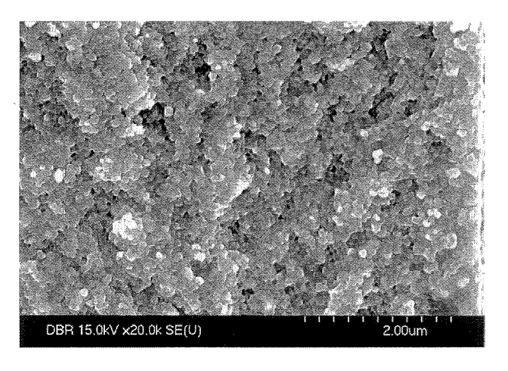
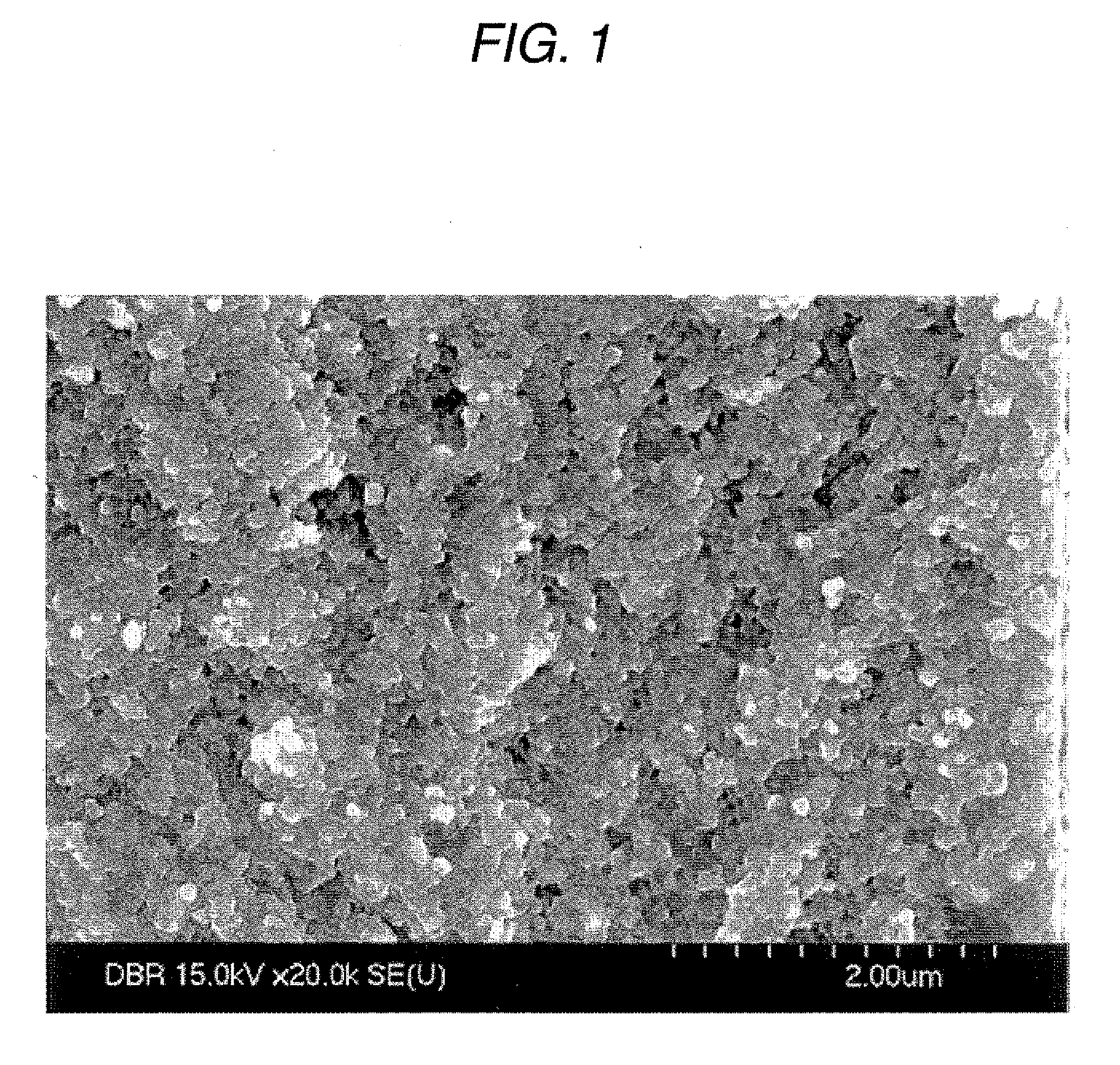
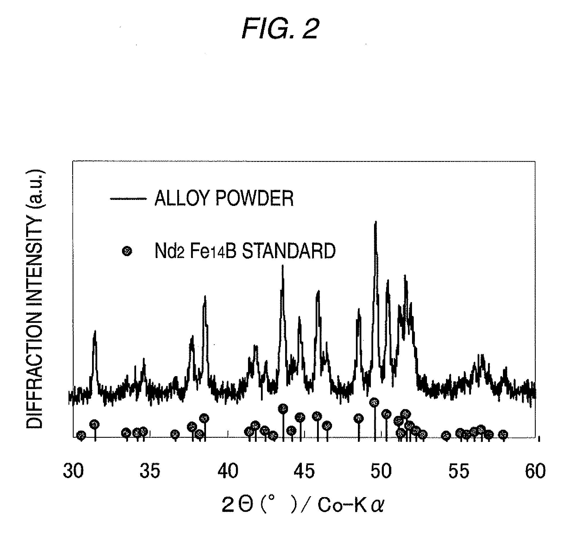
[0122]A rare earth alloy having a component composition of, in terms of mass %, 30% Nd-2% Co-1% B-bal. Fe was melted at 1,350° C., and the melt was projected from an orifice on a Cu-made rotating roll plated with Cr (rotating roll peripheral velocity: 20 m / sec) to obtain a rapid-quenched alloy flake. This rapid-quenched alloy flake was pulverized by a cutter mill and sieved to produce a rare earth alloy powder having a maximum particle diameter of 350 μm or less (hereinafter, sometimes referred to as “Rare Earth Alloy Powder A”). The fracture surface of Rare Earth Alloy Powder A was observed using a Scanning electron microscope (SEM) at a magnification of 20,000. As a result, as shown in FIG. 1, it was confirmed that Rare Earth Alloy Powder A is composed of fine grains having a size of about 0.1 μm. In addition, according to the X-ray diffraction measurement using Kα-ray source of Co, it was confirmed that these grains are Nd2(Fe,Co...

experiment 2

2. Experiment 2

(Heat Treatment)

[0142]With respect to the rare earth magnets of Examples 1 and 4 produced in Experiment 1 (Example 1: the mixing amount of Dy metal powder is 0.3 mass %; Example 4: the mixing amount of 85Dy-15Cu alloy powder is 0.3 mass %), the arced magnet piece was loaded into a vacuum heat treatment furnace and heat-treated at 500 to 1,000° C. for 30 minutes in an Ar atmosphere. Then, the grain size and magnetic characteristics were measured in the same manner as in Experiment 1. In this regard, Example 15 after the heat treatment was observed using a scanning electron microscopy (SEM) in the same manner as Example 5. As a result, a microstructure including a lot of plate-like grains and a grain boundary phase surrounding the peripheries thereof was observed. In addition, as a result of measurement using a transmission electron microscopy (TEM), it was confirmed that diffusion of element Dy into the grain boundary phase is promoted in Example 15 in comparison with ...


PUM

PropertyMeasurementUnit
Grain sizeaaaaaaaaaa
Temperatureaaaaaaaaaa
Fractionaaaaaaaaaa

Abstract

The present invention provides a rare earth magnet, which is formed through at least hot molding, the rare earth magnet containing grains including an R2X14B phase as a main phase, and a grain boundary phase surrounding peripheries of the grains, in which R is at least one element selected from the group consisting of Nd, Pr, Dy, Tb and Ho, and X is Fe or Fe with a part being substituted by Co; in which an element RH is more concentrated in the grain boundary phase than in the grains, in which the element RH is at least one element selected from the group consisting of Dy, Tb and Ho; and the element RH is present with a substantially constant concentration distribution from the surface part of the magnet to the central part of the magnet.

Description

FIELD OF THE INVENTION[0001]The present invention relates to a rare earth magnet and a production process thereof.BACKGROUND OF THE INVENTION[0002]Conventionally, a rare earth magnet such as Nd—Fe—B type has been used in a room temperature environment, for example, in a voice coil motor (VCM) of a hard disk drive or in a magnetic resonance imaging (MRI) device, and therefore, heat resistance has almost never been required so far.[0003]In recent years, this type of rare earth magnet is expanding its application, for example, to an EPS motor of general vehicles, a driving motor of hybrid electric vehicles (HEV), or a motor for FA (robot or machine tool). Along with such expansion of the application range, the rare earth magnet is required to have heat resistance and be capable of withstanding use in a relatively high temperature environment. This tendency is strong particularly in the application to automobiles.[0004]The most common method for elevating the heat resistance of the rare...

Claims


Application Information

Patent Timeline
IPC IPC(8): C22C38/00B22F3/12B22F1/17
CPCB22F1/025H01F41/0293B22F2998/00B22F2998/10C22C28/00C22C33/0278C22C38/002C22C38/005C22C38/10C22C2202/02H01F1/0576H01F41/0266B22F3/12B22F2207/01B22F3/02B22F3/14B22F3/24B22F1/17
Inventor SUZUKI, SHUNJIHASHINO, HAYATOHIRAOKA, MASAHIROYABUMI, TAKAO
Owner DAIDO STEEL CO LTD
Why Eureka
Try Eureka