Radial roller bearing, in particular for storing shafts in wind turbine transmissions

a technology of rotating roller bearings and shafts, which is applied in the direction of roller bearings, mechanical equipment, machines/engines, etc., can solve the problems of no longer being an adequate lubricating film, high tangential stress in the surface, and destroying the lubrication film, etc., to increase the bending fatigue strength, increase the inherent compression stress, and produce additional inherent compression stress

Inactive Publication Date: 2010-01-28
SCHAEFFLER TECH AG & CO KG
View PDF5 Cites 6 Cited by
  • Summary
  • Abstract
  • Description
  • Claims
  • Application Information

AI Technical Summary

Benefits of technology

[0009]Accordingly, as claimed in claim 2, in one particularly advantageous refinement of the radial roller bearing designed according to the invention, the hollow rollers have the same axial length as the other roller bodies and are preferably formed with a total inherent compression stress of between −400 MPa and −800 MPa on their inner envelope surfaces. In this case, designing the hollow rollers to have the same axial length as the other roller bodies contributes to keeping the radial roller bearing load capability losses, which result from the design of the hollow rollers, as low as possible, while the value of the inherent compression stress of between −400 MPa and −800 MPa represents an optimum with regard to the effectiveness of high inherent compression stresses on the inner envelope surfaces of the hollow rollers in order to increase their bending fatigue strength.
[0010]According to claim 3, a first possible way to produce additional inherent compression stresses on the inner envelope surfaces of the hollow rollers of the radial roller bearing designed according to the invention in a simple and cost-effective manner is to mechanically process the inner envelope surfaces of the hollow rollers by compacting using hard rolling. This processing method is a shaping process which does not involve cutting and is based on the idea that the strength of machined surfaces is increased under the contact pressure of hardened roller bodies, such as rollers or balls. This is done by plastic deformation of the profile peaks in such a way, that the surface pressure that occurs between the rollers and the material produces three-dimensional compression stresses in the material, which reach the yield stress of the material and therefore result in local plastic deformation or strengthening of the surface, and therefore in high inherent compression stresses in the edge area. In this case, additional inherent compression stresses of up to 31 1000 MPa can be produced in the processed surface, depending on the material and the heat-treatment state. A further positive effect of this method is the simultaneous major reduction in the surface roughness, which leads to a further improvement in the bending fatigue strength of the hollow rollers.
[0011]According to claim 4, a second possible way to produce additional inherent compression stresses in the inner envelope surfaces of the hollow rollers of the radial roller bearing designed according to the invention is to mechanically process the inner envelope surfaces of the hollow rollers by shot blasting. In this surface treatment method, which is also known as shot-blasting strengthening, a blast agent of round shots is used, which is thrown at the surface to be treated at high speed. This is generally done by means of fan-blower, compressed-air or injector blasting installations, in which spherical grains used for blasting are accelerated to a high speed and are impacted onto the surface to be processed. This results in strengthening and plastic deformation in the area of the surface which, in the case of the hollow rollers, depending on the material that is used, produces inherent compression stresses in their inner envelope surfaces of up to the level of the yield limit of the material in the respective heat-treatment state. In order to ensure that the surface roughness is not excessively adversely influenced, technically worthwhile compression stresses resulting from shot blasting are in the range between −800 and −1000 MPa. A further positive effect of this method is the simultaneous major increase in the corrosion resistance of the processed surfaces of corrosion-resistant steels.
[0012]Finally, as an alternative third possible way to produce additional inherent compression stresses in the inner envelope surfaces of the hollow rollers of the radial roller bearing according to the invention, claim 5 also proposes that the inner envelope surfaces of the hollow rollers be mechanically processed by calibration. In this case, the expression calibration should be understood as meaning that a hardened body having an external diameter which is slightly larger than the internal diameter of the bore in the hollow rollers is forced through the hole in the hollow roller, likewise resulting in local plastic deformation or strengthening of the surface, and creating high inherent compression stresses in the edge area. A steel ball has been found to be most suitable as a hardened body for this purpose, although a cylindrical body with rounded edges can also be used. The additional inherent compression stresses which can be produced in the processed surface are in this case up to −500 MPa, depending on the material, with a major reduction in the surface roughness also being achieved here, as an advantageous side effect.
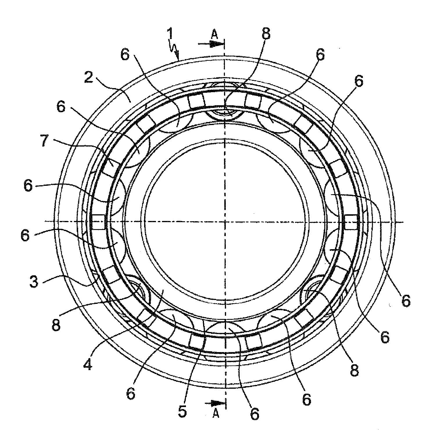
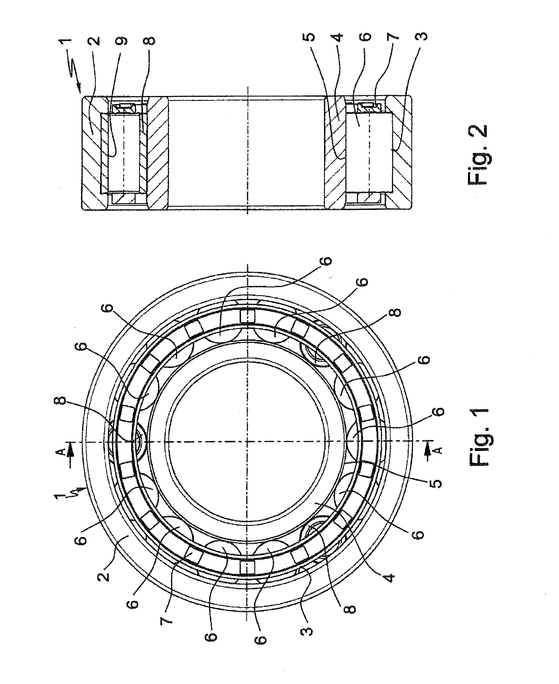
[0013]The radial roller bearing designed according to the invention therefore has the advantage over the radial roller bearings that are known from the prior art that, while greatly retaining its original performance features such as load capacity, installation space and service life, in order to avoid slip between the roller bodies and the bearing rings it is equipped with hollow rollers, which have an increased bending fatigue strength and fatigue strength as a result of a mechanically produced increase in the inherent compression stresses in their inner envelope surfaces, which already exist as a result of the heat treatment, thus compensating for local stress peaks in the inner envelope surfaces. These advantages are in this case achieved even if the roller bodies are not guided by a bearing cage, but guide themselves, as in the case of fully rolling bearings.

Problems solved by technology

In consequence, the rotation speed of the roller body set is less than the kinematic rotation speed, so that the roller bodies are in a kinematically non-optimum state, as a result of which slip occurs between these roller bodies and at least one raceway.
However, the lubrication film is destroyed in the event of a sudden change in the rotation speed or load, as a result of which there will no longer be an adequate lubricating film at the contact points where the slip occurs within a very short time.
This large speed difference between the raceway and the roller bodies as well as the lack of a separating lubricating film therefore results in high tangential stresses in the surfaces of the raceway and of the roller bodies, which are associated with very severe wear, such as roughening of the raceways, material being torn off and rubbing marks, generally in conjunction with micropitting, thus leading to premature failure of the radial roller bearing.
However, in practice, it has been found that the hollow rollers, which are subject Lo continuous bending fatigue load as a result of their permanent deformation, in radial roller bearings such as these represent potential weak points of the roller bearing in terms of their load capability and fatigue strength, thus resulting in reduced load-carrying capability and a shorter life of the roller bearing.
For example, it has been found that local stress peaks occur, in particular, on the inner envelope surfaces of the hollow rollers, leading to cracking and finally to fracture of the hollow rollers during long-term operation of the roller bearing.
This was due in particular to the use of standard roller-bearing steel for the hollow rollers and their standard heat treatment, in which the hollow rollers were provided with a continuously martensitic structure by hardening at a temperature of 860° C., quenching in an oil or salt bath and tempering at 190±10° C., a very high level of hardness of which structure admittedly ensures that the hollow rollers have high rolling-over strength, although the low ductility and the lack of inherent compression stresses are unsuitable, in particular for the continuous bending fatigue loads on their inner envelope surfaces.
One obvious measure to avoid such stress concentrations would admittedly be to increase the dimensions of both the hollow rollers and the other roller bodies, but this would necessarily result in an increase in the total space required for the bearing and an increase in the production costs for the roller bearing.

Method used


Image

  • Radial roller bearing, in particular for storing shafts in wind turbine transmissions
  • Radial roller bearing, in particular for storing shafts in wind turbine transmissions

Examples


Embodiment Construction

[0006]According to the invention, in the case of a radial roller bearing as claimed in the preamble of claim 1, this object is achieved in that the inner envelope surfaces of the hollow rollers are formed by way of specific mechanical processing to have further inherent compression stresses of at least −200 MPa, which are superimposed on their maximum load stress in addition to the inherent compression stresses which result from their heat treatment.

[0007]The invention is therefore based on the realization that, by mechanically introducing additional inherent compression stresses into the inner envelope surfaces of the hollow rollers, the stresses, together with the inherent compression stresses resulting from the heat treatment of the hollow roller, counteract the tensile stresses which act during bearing operation, it being possible to compensate for the local stress peaks in the hollow rollers, which lead to cracking and finally to fracture of the hollow rollers, and, therefore, ...


PUM


Abstract

A radial roller bearing for shafts in wind turbine transmissions, which includes an external bearing ring with an inner runway, an internal bearing ring arranged coaxial thereto which has an outer raceway and roller bodies on runways between bearing rings spaced circumferentially by a bearing cage and distributed uniformly on a circumference replaced by hollow rollers. To prevent slip, the hollow rollers have a greater diameter and lower modulus of elasticity ensuring, in a load-free state, continuous contact by the radial roller bearing with the bearing rings and continuous drive for the bearing cage and roller bodies at kinematic rotation speed. The hollow rollers have increased bending fatigue strength, and their inner envelope surfaces are formed by mechanical processing for further inherent compression stresses of at least −200 MPa, superimposed on the hollow rollers maximum load stress along with the inherent compression stresses resulting from their heat treatment.

Description

FIELD OF THE INVENTION[0001]The invention relates to a radial roller bearing according to the features which form the preamble of patent claim 1, and it can be implemented particularly advantageously on bearings which run at a very low load at least at times, for example for the bearing of shafts in wind power transmissions.BACKGROUND TO THE INVENTION[0002]A person skilled in the art of roller bearing technology will in general be aware that radial roller bearings have an optimum kinematic operating state when sufficiently loaded, at which the roller bodies roll on the raceways of the inner and of the outer bearing ring, without sliding. Furthermore, in the case of radial roller bearings which are operated on low loads at least at times, it is known that the roller body set which comprises the roller bodies and their bearing cage does not rotate at the kinematic rotation speed because of the friction in the bearing or because of the high mass force of the roller body set and the con...

Claims


Application Information

Patent Timeline
Patent Type & Authority Applications(United States)
IPC IPC(8): F16C33/34
CPCF03D11/0008F05B2240/54F16C19/26F16C2240/18F16C33/34Y02E10/722F16C27/04F16C19/50F16C33/46F16C2360/31F16C2361/61F03D80/70Y02E10/72
Inventor ENDRES, BERNDHOFFINGER, CHRISTIANMERKLEIN, CARSTEN
Owner SCHAEFFLER TECH AG & CO KG
Why Eureka
Try Eureka