
Cellular gradient polymer composites

a gradient composite and polymer technology, applied in the field of cellular composite products, can solve the problems of reduced stiffness and early failure, limited design of polymer-based gradient composites, and high stress concentration, and achieve the effects of improving mechanical modulus and strength of porous composites, and controlling cellular structur

Inactive Publication Date: 2010-01-28
ECOLE POLYTECHNIQUE FEDERALE DE LAUSANNE (EPFL)
View PDF5 Cites 14 Cited by
  • Summary
  • Abstract
  • Description
  • Claims
  • Application Information

AI Technical Summary

Benefits of technology

[0023]A porous and reinforced polymer composite product is proposed, preferably obtained through a solvent-free process comprising the precise placement of fibres and / or fillers followed by the gas foaming of the composite preform. The composite product has a controlled cellular structure based on polymers with fillers, short, long or continuous fibres and combination of them. Gradients of fibre volumes (when fibres are used) are controlled through the placement of filaments, yarns or commingled yarns; fibre contents up to 65 vol % can be reached locally. Porosity can be varied from 0 up to 90% in volume and porosity gradients are achieved by varying the gas foaming parameters. The process can combine different types of gradients in order to prepare polymer foams with tailored variations of filler / fibre volumes and of porosity in several directions of the product. Fibres improve the mechanical modulus and strength of the porous composite while providing desired anisotropy and functional properties.

Problems solved by technology

Indeed uncontrolled morphology of pores induces stress concentrations, reductions of stiffness and early failure.
This technique allows only very specific and limited design of polymer-based gradient composites.
However this type of scaffold is highly deformable and has poor mechanical properties (Cima, Vacanti et al.
It is to note that mechanical properties of polymer foams always appear to be low, in particular if intended use is hard tissue engineering.
Furthermore, these reinforcements can bring anisotropy, gradient of properties and functions.
Despite bone grafts is a routine procedure in orthopaedic surgery, no satisfactory bone substitutes are currently available.
The use of synthetic bone substitutes is increasing; however, in a review of clinically available bone substitutes in France, no polymer scaffold was available for orthopaedic applications (Mainard, Gouin et al.
Most of the synthetic bone grafts used are made of ceramic such as calcium phosphates, which do not allow load-bearing application due to their low toughness and brittle mechanical behaviour.
However, particles and short fibres do not reinforce the polymeric foams sufficiently.
However, to our knowledge no continuous fibres have been introduced into thermoplastic foams and an interconnected and micro-sized porosity obtained.
Moreover no gradients in fibre volumes have yet been considered in the case of porous or cellular structures.
Current ceramic implants have an intrinsic low toughness and can not easily be shaped or screwed; that is why they are not considered as ideal.
There is also risk of inflammation induced by micro movements between implant and bone, because of modulus mismatch.

Method used


Image

  • Cellular gradient polymer composites
  • Cellular gradient polymer composites
  • Cellular gradient polymer composites

Examples


example 1

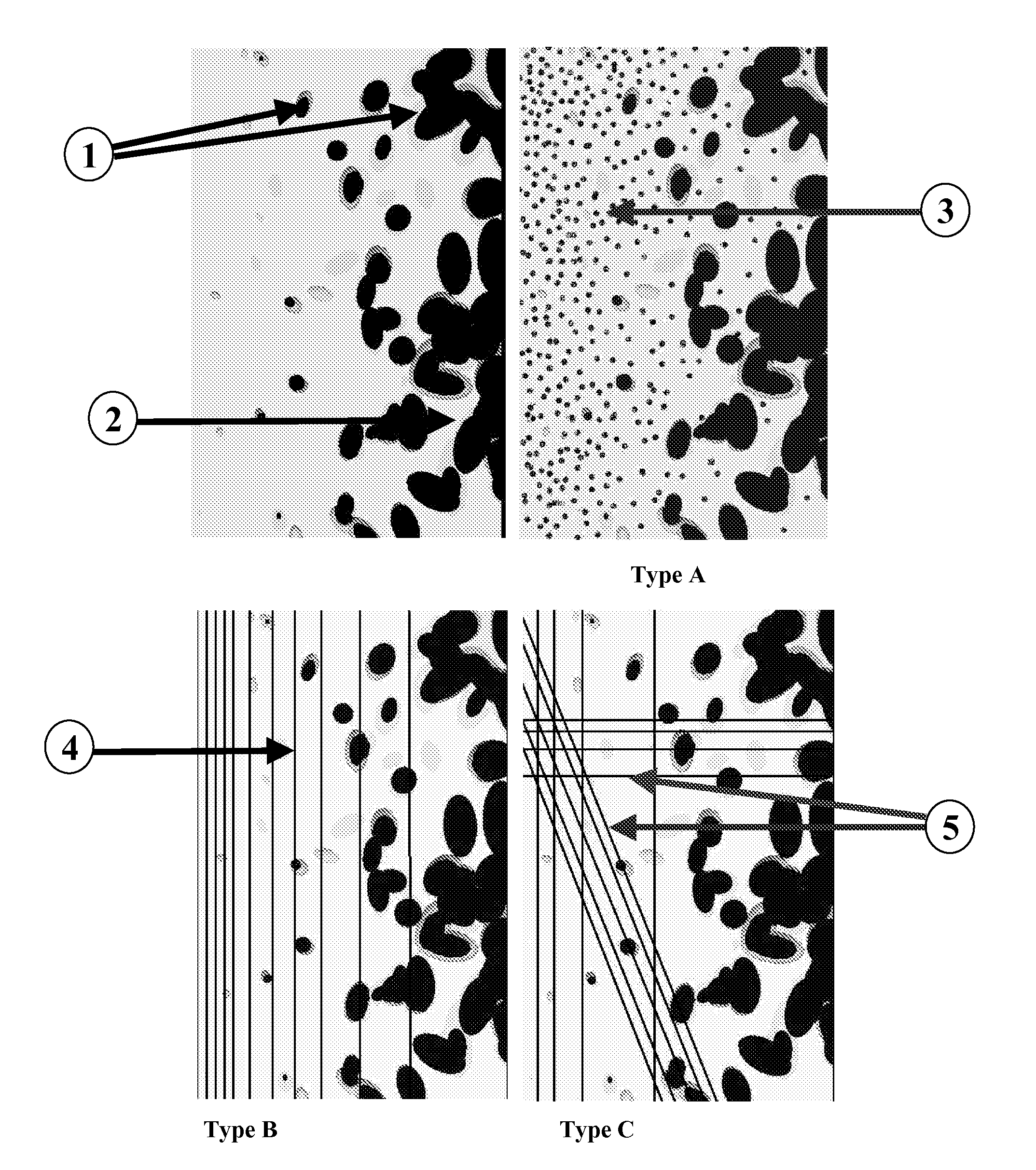
A Composite Product Combining Gradients of Fillers and of Porosity

Type A

[0071]The objective of this example is to illustrate how to obtain a composite porous structure of type A (FIG. 1).

[0072]First 5 g of PLA+5% β-TCP (PLA-5TCP), and 5 g of PLA+10% β-TCP (PLA-10TCP) are extruded under an inert atmosphere, using a micro-extruder (Micro5, DSM; the Netherlands). The following parameters are used: screw rotation speed 100 rpm, residence time 4 min and set temperature 200° C. Extruded compounds are then dried and cut into 1 cm long rods. Into a 50 mm diameter cylinder mould, a paper cylinder of 35 mm diameter is placed inside. Inside this cylinder, the 5 g of PLA-5TCP are placed, and on the outside the 5 g of PLA-10TCP are added. The paper cylinder is then removed, leading to a gradient of β-TCP concentration in the composite.

[0073]In a second step, foaming is carried out. The mould prepared as previously described is put into the autoclave. After tightly closing, pressure is increased ...

example 2

Composite Product Combining Gradients of Fibres and of Porosity

Type B

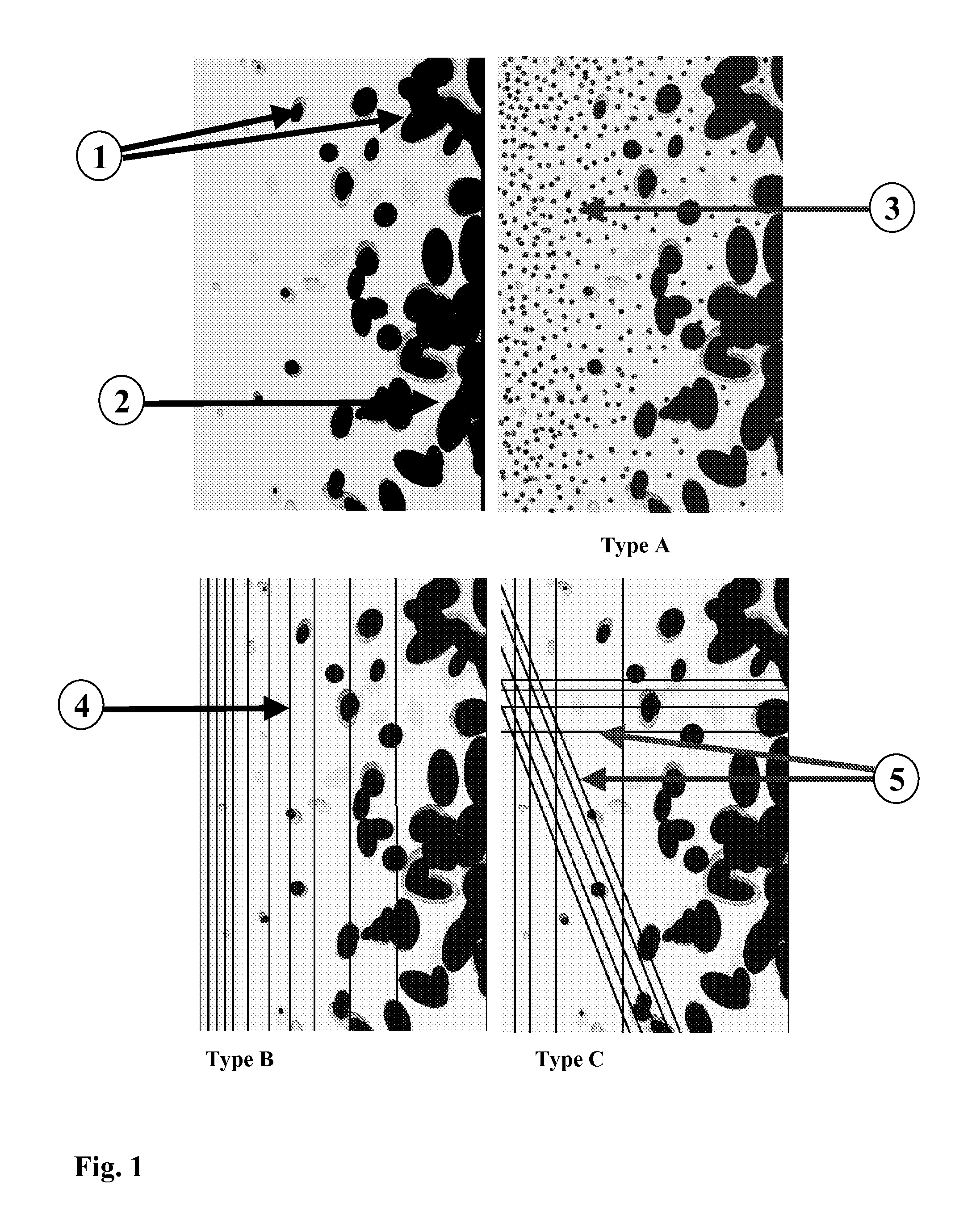
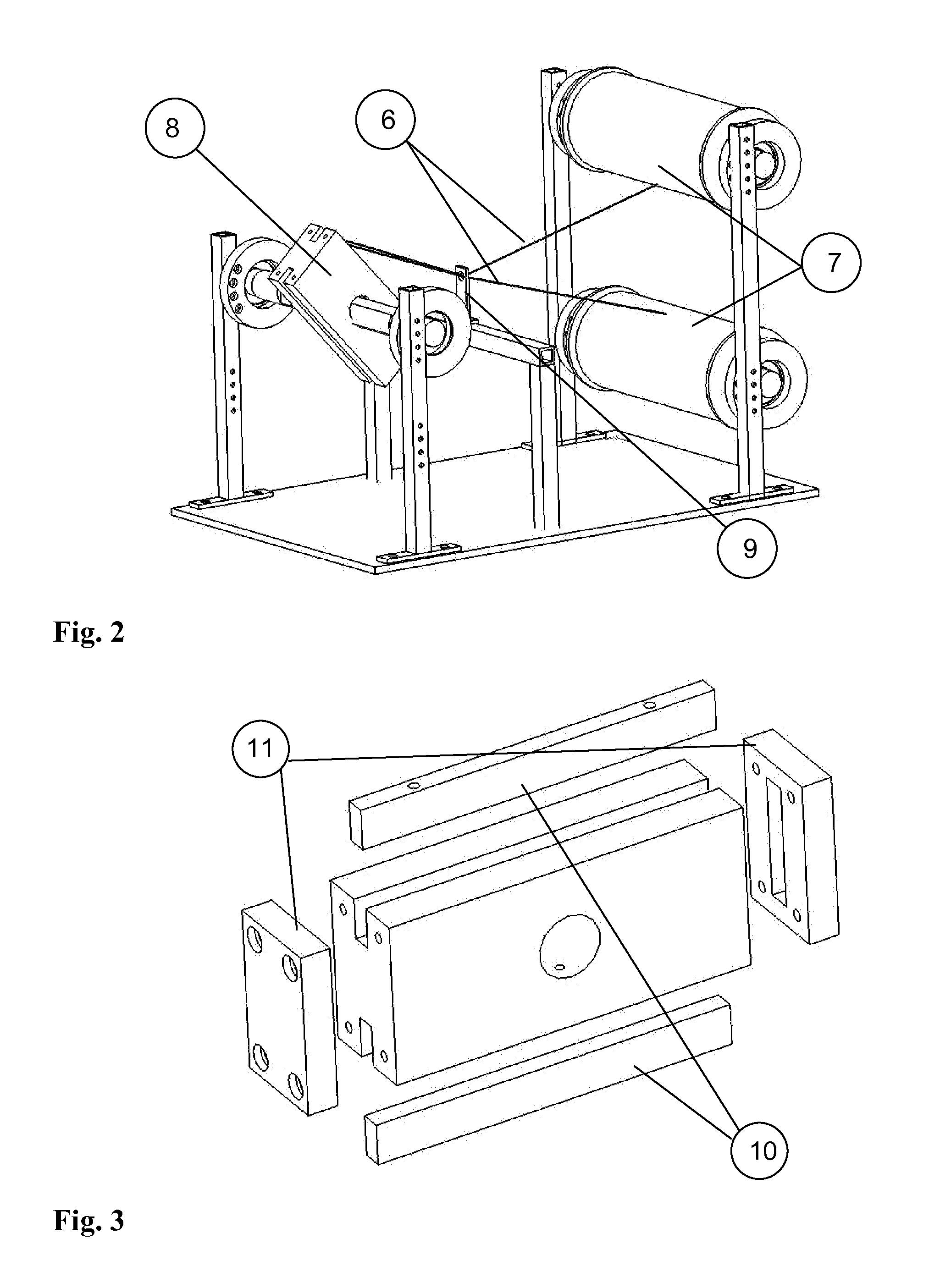
[0074]Processing steps and microstructure of type B composites with fibre volume gradients is described. The winding set-up is used to place polyamide (PA12) fibre bundles here with 32 monofilaments and carbon fibres (CF), in this case bundles of 250 monofilaments, around the mould (8) (FIGS. 2 and 3). The fibre volume fraction of carbon fibres at the external sides of the beam is 15%. FIG. 6 depicts the processing parameters used for the preconsolidation and final consolidation when the thermoplastic material is processed at 200° C. For example, FIG. 7 depicts the section of a Polyamide 12 (PA12) / carbon fibre (CF) composite having a fibre-free centre (16) surrounded by a fibre-rich region (4). The FIG. 7 shows also that the relative position between fibre bundles could be maintained during the solidification steps. In horizontal and vertical directions, a bundle placement precision of less than 500 μm and 200 μm r...

example 3

Composite Structure Combining Gradients of Fibres and of Porosity

Type B and C

[0076]The main challenge is here to combine fibre volume and porosity gradients, and more specifically, to preserve the initial fibre volume gradient when applying the gas foaming process to the system. The final fibre-reinforced foams have porosities ranging from 0% or more up to 90%.

[0077]The example is based on a bioresorbable polymer, Poly(L-lactic acid) (PLA) reinforced with glass fibres, but the method is not restricted to this material system.

[0078]Continuous conventional E glass fibres are winded progressively around the holder (FIG. 4) to form several layers with different fibres volumes and to keep fibres stable and oriented during foaming. The holder is then put into a cylindrical mould for the pressurised chamber, and the PLA pellets (15 g) are added to the fibres. PLA pellets can be replaced or combined with PLA fibres winded with the glass fibres to form commingled yarns. Gas foaming is then c...


PUM

PropertyMeasurementUnit
Fractionaaaaaaaaaa
Fractionaaaaaaaaaa
Fractionaaaaaaaaaa

Abstract

The invention relates to a foamed polymer composite product incorporating several fillers and / or fibres and several pores characterized by the fact that it shows two distinct gradients, namely a filler and / or fibre density gradient and a pore density gradient. The polymer composite according to the invention may advantageously be used in tissue engineering, bone replacement, consumer goods, transportation or in any other suitable field. The invention also includes a process for manufacturing said polymer composite.

Description

FIELD OF THE INVENTION[0001]This invention relates to cellular composite products based on polymers incorporating fillers and / or fibres and the method to process them. Such composite structures may advantageously be used in tissue engineering, bone replacement, consumer goods, transportation or in any other suitable field.BACKGROUND[0002]Porous materials are numerous in nature (bone, wood, sponge . . . ) as well as in synthetic materials (foams, honeycomb for sandwich structures, . . . ). Bone structure for instance, has been optimised by nature during millions of years, offering performance in terms of lightness, stiffness, strength, shapes, porosity, healing performance etc. As bone is basically a composite of natural ceramic and polymer materials with different distribution of porosity and mechanical properties, it is of interest to mimic this material and structure.[0003]Any synthetic composite offering the properties of natural bone or based on a similar microstructure will ope...

Claims


Application Information

Patent Timeline
IPC IPC(8): A61K47/30A61K31/66B32B5/08
CPCA61F2/28A61L27/56A61F2/30965A61F2002/30004A61F2002/30006A61F2002/30011A61F2002/30062A61F2002/30065A61F2002/30957A61F2210/0004A61F2210/0071A61F2250/0014A61F2250/0015A61F2250/0023A61L27/446A61L27/46A61F2/3094
Inventor BOURBAN, PIERRE-ETIENNEBUHLER, MANUELMANSON, JAN-ANDERS EDVINMATHIEU, LAURENCE MARCELLE MONIQUEPIOLETTI, DOMINIQUESTADELMANN, VINCENT
Owner ECOLE POLYTECHNIQUE FEDERALE DE LAUSANNE (EPFL)
Learn More