Large format thermoelectric infrared detector and method of fabrication

a thermoelectric infrared detector and large-scale technology, applied in the field of infrared detectors, can solve the problems of photon detectors undesired cooling to cryogenic temperatures, change in the temperature of detectors, change in the electrical resistivity or electrical polarization of detector materials, etc., to enhance the ir absorbing enhance the energy absorption ability of the plate structure, and enhance the effect of infrared radiation absorption

Active Publication Date: 2010-02-11
NYTELL SOFTWARE LLC
View PDF7 Cites 65 Cited by
  • Summary
  • Abstract
  • Description
  • Claims
  • Application Information

AI Technical Summary

Benefits of technology

[0025]An electrical connection between the respective hot junctions is made, such as by using a plate structure material that is electrically conductive or by disposing a conductive trace upon the plate structure that connects the respective hot junctions. An infrared absorbing material is preferably deposited over the upper major surface of the plate structure to enhance the plate structure's IR abs

Problems solved by technology

Thermal detectors on the other hand, depend upon absorbing incident infrared radiation (IR) from the observed scene, resulting in a change in the temperature of the detector.
This in turn results in a change in electrical resistivity or electrical polarization in the detector material or in a voltage being generated by the detector.
Additionally, photon detectors undesirably require cooling to cryogenic temperatures, typically 77K (−321 F) or below.
All infrared detectors are fundamentally limited by both the temperature of the detector itself as well as by the temperature of the background in which the object of interest resides.
For applications where the background temperature is approximately room temperature, it has been shown that cryogenic cooling of photon detectors does not significantly increase sensor sensitivity.
The slight enhanced sensitivity with cryogenic cooling however, significantly increases the cost and decreases the reliability of the overall system.
While system cost is a significant consideration in the above applications, overall power consumption of an infrared imaging system is also critical, particularly for mobile applications.
Batteries are inefficient, heavy, and greatly limit the life of portable infrared imaging systems.
A significant source of power consump

Method used


Image

  • Large format thermoelectric infrared detector and method of fabrication
  • Large format thermoelectric infrared detector and method of fabrication
  • Large format thermoelectric infrared detector and method of fabrication

Examples


Embodiment Construction

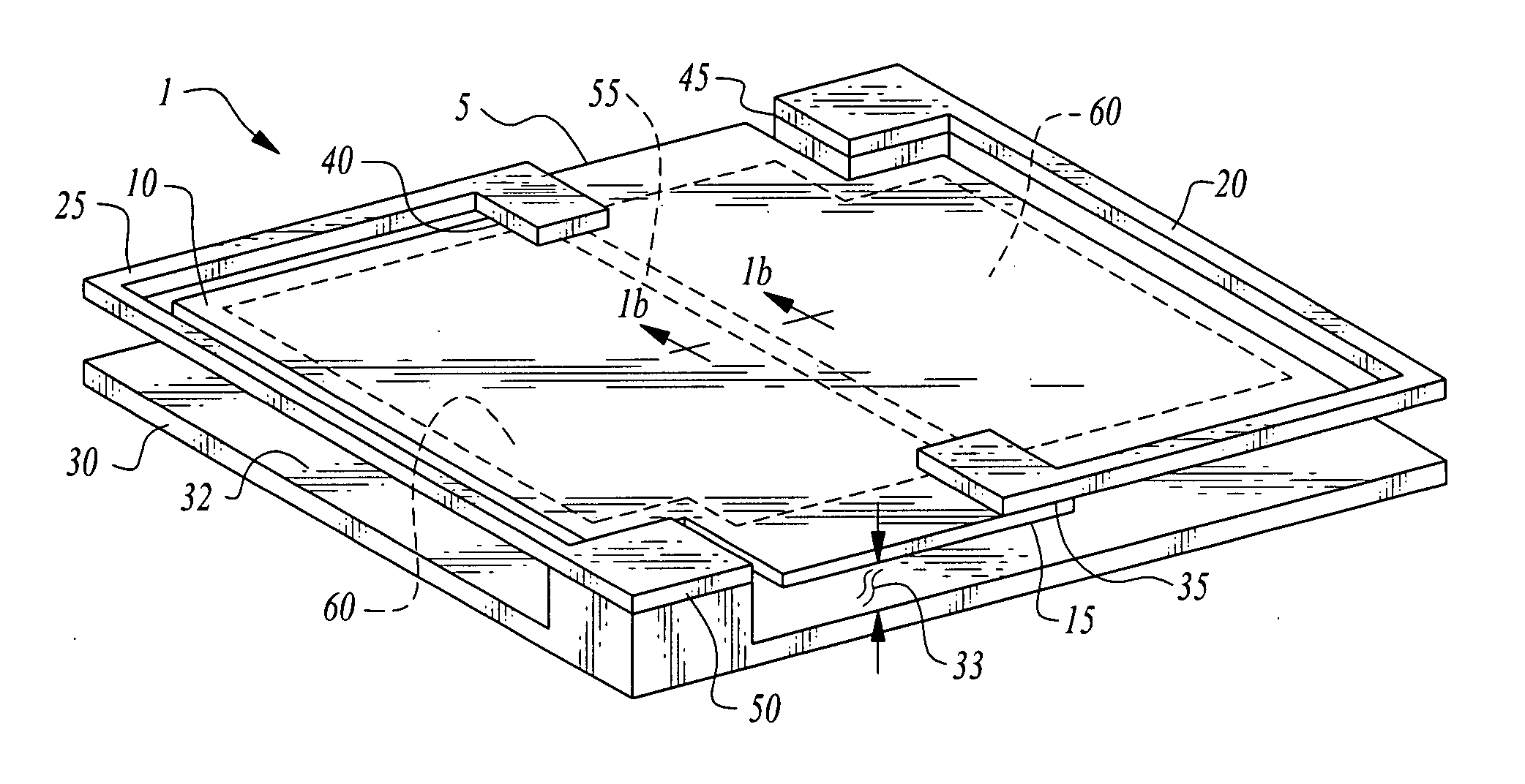
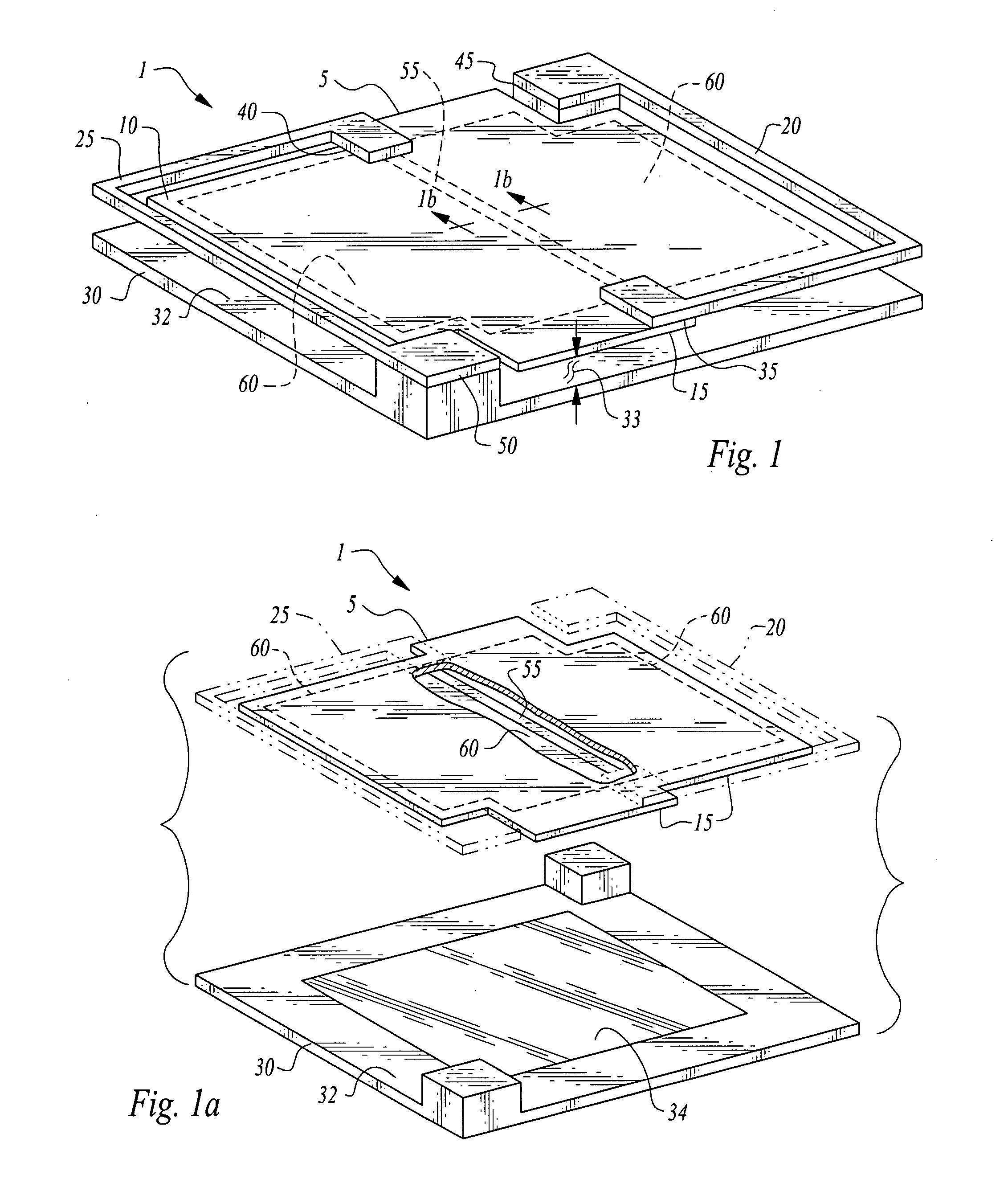
[0040]Turning now to the figures wherein like numerals define like elements among the several views, FIGS. 1 and 1a illustrate a preferred embodiment of detector 1 of the invention.

[0041]Detector 1 comprises a plate structure 5 comprising an upper major plate surface 10 and a lower major plate surface 15. Plate structure 5 functions as an infrared radiation collector of IR energy incident upon upper major plate surface 10.

[0042]Plate structure 5 is supported by at least two thermoelectric structures referred to as first thermoelectric structure 20 and second thermoelectric structure 25. First and second thermoelectric structures are preferably elongate, narrow beams or legs comprising one or more thermoelectric materials such as Bismuth-Telluride, Bismuth-Antimony-Telluride, polysilicon, polysilicon / germanium or equivalent materials.

[0043]Plate structure 5 is suspended above a substrate 30 by means of the thermoelectric structures so as to define a hollow volume and an offset distan...


PUM


Abstract

The thermoelectric detector consists of an absorber structure supported by two electrically connected beams made of thermoelectric materials such as polysilicon, polysilicon/germanium, bismuth-telluride, skutterrides, superlattice structures, nano-composites and other materials. One end of the thermoelectric beam connects to the absorber structure; the other end connects to the substrate. Infrared radiation incident on the absorber heats up the absorber, resulting in a temperature gradient along the length of the thermoelectric legs, and generating an electrical voltage. The detector arrays are fabricated using micromachining process. The absorber structure is formed over a sacrificial material that is removed at the end of the processing, leaving the detector suspended and thermally isolated. The sacrificial processing method enables the production of small pixel thermoelectric detectors in large two-dimensional arrays with high sensitivity.

Description

CROSS-REFERENCE TO RELATED APPLICATIONS[0001]This application claims the benefit of U.S. Provisional Patent Application 60 / 809,466, filed on May 30, 2006, entitled “Large Format Thermoelectric Infrared Detector and Method for Fabrication” pursuant to 35 USC 119, which provisional application is incorporated fully herein by reference.STATEMENT REGARDING FEDERALLY SPONSORED RESEARCH AND DEVELOPMENT[0002]Not applicable.DESCRIPTION[0003]1. Field of the Invention[0004]The invention relates to the field of infrared detectors and a method of their fabrication. Specifically, the invention relates to the use of thermoelectric sensors for the observation of temperature differences in a scene.[0005]2. Background of the Invention[0006]Detection of infrared signals is primarily achieved by the use of either photon detectors or thermal detectors.[0007]Photon detectors depend upon the absorption of photons from an observed scene to break electrons or holes free on the selected detector material. D...

Claims


Application Information

Patent Timeline
IPC IPC(8): H01L35/02H01L21/50
CPCH01L35/32G01J5/12H10N10/17
Inventor HSU, YING
Owner NYTELL SOFTWARE LLC
Why Eureka
Try Eureka