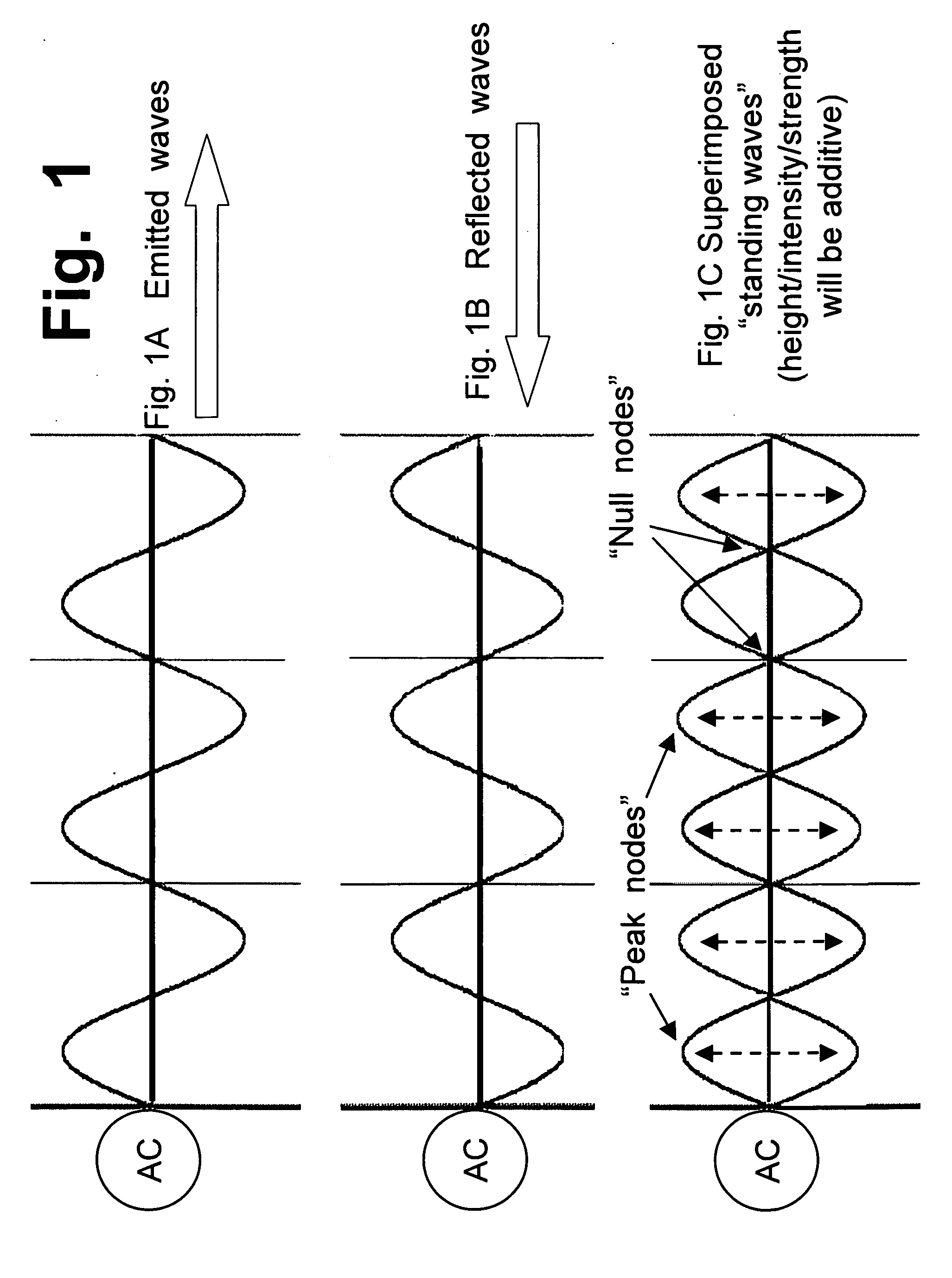
However, that drawing fails to show another result which is very important in what actually happens in a
standing wave.
However, that depiction might confuse people, so it usually is not shown in drawings of “standing
waves”.
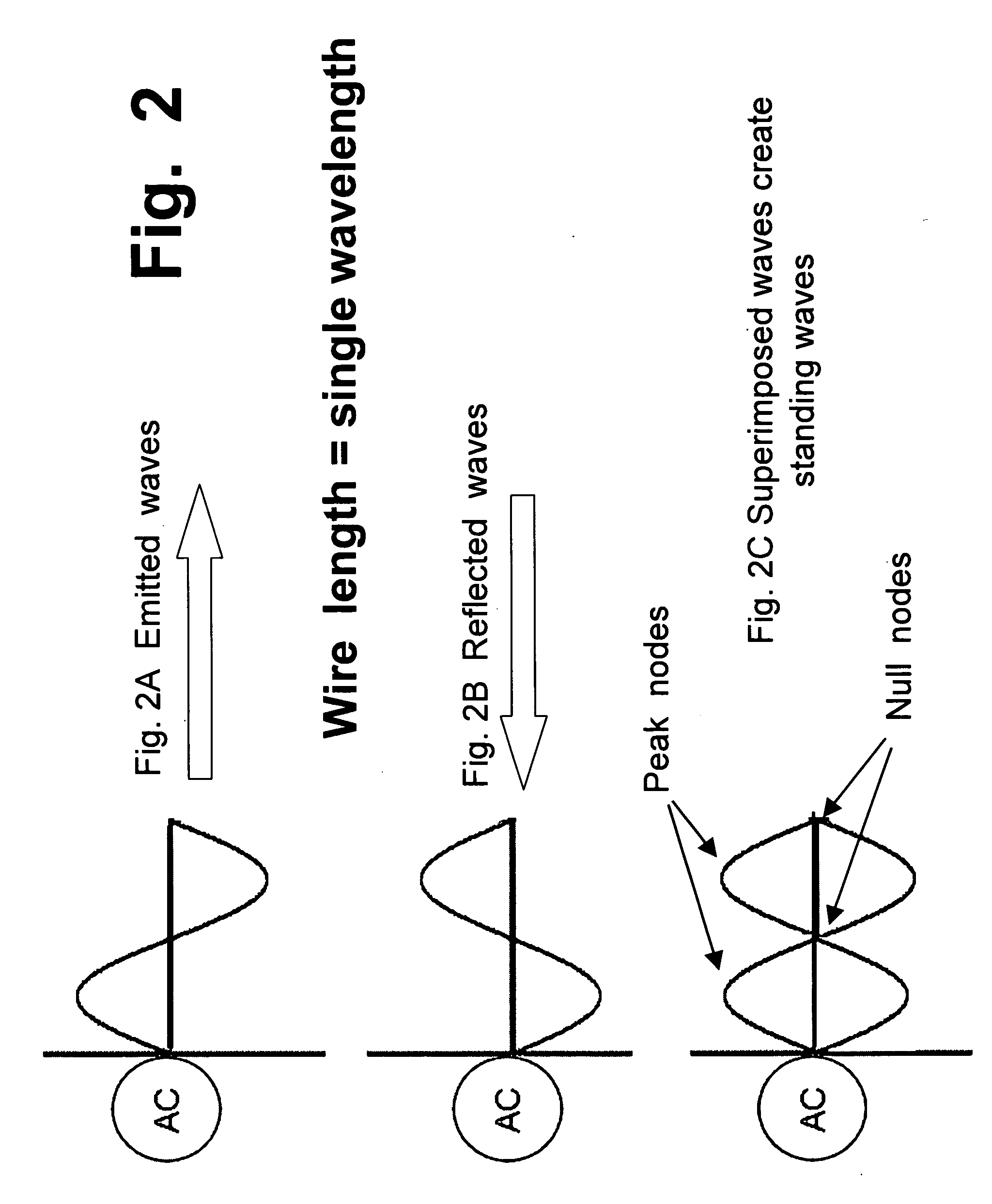
If a wire has a long and tapered tip, then the reflected wave might become somewhat diffused, and it might lose some portion of the “
clarity” of the wave.
However, since wavelengths in the frequencies of interest herein are hundreds of meters long, the type of tip created by a conventional
wire cutter will not create any significant
diffusion, in a reflected wave.
And, unlike the white-painted walls of a room, there is not a large area that is available, at the tip of a wire, that can create scatter, spread, or
diffusion.
However, those are not the types of natural and stable responses that can be created by a simple, basic
system consisting of nothing more than: (i) a wire having a
fixed length and a “reflective” tip; and (ii) an
AC power source with a frequency that can be “tuned” until it creates a resonant response in any
wire segment having a suitable length.
However, those examples are not relevant to
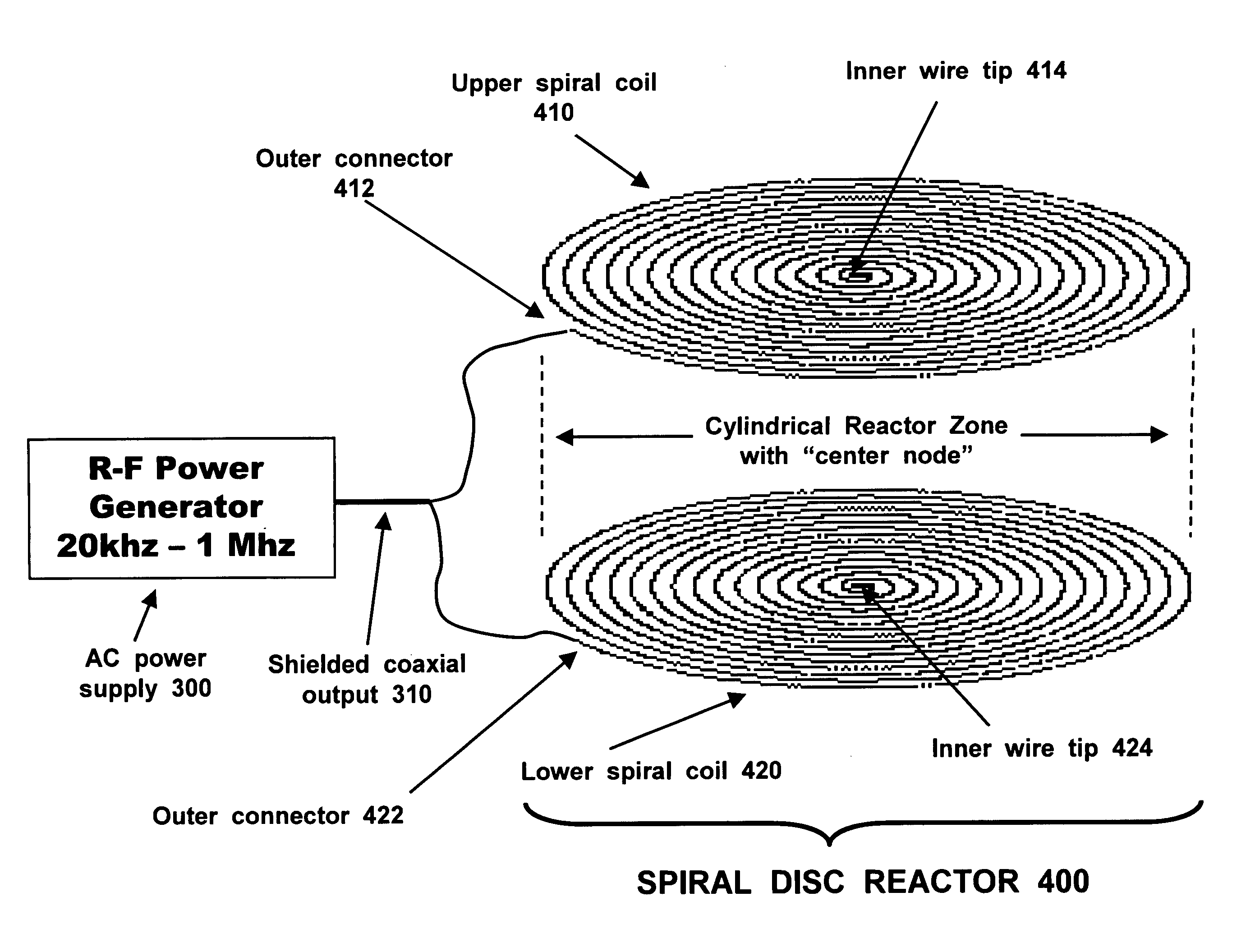
spiral coil reactors, which will use an approach that involves tuning and adjusting the frequency of the voltage that is being supplied to a reactor, until a resonant response is observed in coils with fixed and unchanging lengths.
Therefore, in “high-performance” reactors, any added tuning element or other nonessential component will create an additional opportunity and location where something might fail.
Among other things, there will be some loss and emission of power (both along the length of the wire, and at its end) which will erode the power and “peak heights” of the
reflected waves; and, there will be some “reflection and bounceback” of the second-pass reflected wave, when it reaches the “entry” end, where the wire is connected to the power supply.
Instead, the feedback signals will actively interfere with the initial output, in ways that aggressively
undercut its power and reduce its efficiency.
They are not neutral, and they cannot be ignored; therefore, they become actively disruptive and detrimental, in a
system that is struggling to work efficiently.
The signals from any other
station, even at the closest adjacent frequencies being used by other radio stations, are so much weaker that they can be easily filtered out, and cannot even be heard, on any decent radio tuned to a
station that is
broadcasting at a certain frequency.
However, in an
alternating current system, where the voltage follows a “
sine wave” function that alternates back and forth between positive and negative values, 60 times every second, while following a rounded and sloping curve without any “square blocks”, that type of multiplication becomes much more complicated.
As a result, if instantaneous
peak current values are not aligned properly (in time) with peak voltage values, the system will suffer from problems that are referred to by phrases such as “
out of phase” and “unsynchronized”.
If a motor or other device is forced to perform in an “
out of phase” manner (or, stated in different but consistent terms, if the device has a low
power factor), it cannot and will not perform with optimal efficiency.
“Out-of-phase” problems are common.
By contrast, if the current and voltage cycles are out-of-alignment, and out-of-phase, its
power factor will be hindered, reduced, and damaged.
Although various types of devices (such as radio and
television receivers) have both (i) a tuning device which uses quarter-
wave resonance, and (ii) an
amplifier circuit that uses L / C
resonance, to the best of the Applicant's knowledge, no one has ever previously created or identified any electrical components that deliberately create and utilize both types of
resonance simultaneously, with the possible exception of components that may exist in extremely large “particle accelerators” (also called “atom smashers”) that cost billions of dollars to build.
However, more than 50 years of research on
tokamak reactors still has never created even a single instance of net
power output, where the amount of energy released by
hydrogen-to-
helium fusion, in a
tokamak reactor, was greater than the amount of energy required to conduct that test.
That is a tragic result, because of the extraordinary promise and potential of fusion reactors, if they could only be created.
First, a fusion reactor would not require, create, or involve
uranium,
plutonium, or any other “heavy elements” of a type that create toxic and dangerous radioactive wastes, and that also create fears and threats of uncontrolled nuclear weapons, “dirty bombs”, accidental releases, etc.
Although success cannot be assured, the spiral disc
reactor design disclosed herein merits very serious consideration and careful testing, to determine whether such discs (in very large sizes, and run at very high power levels) will be able to create and sustain
hydrogen-to-
helium fusion reactions that will create net
power output.
However, despite more than 50 years of research (and countless billions of dollars in funding), no one has ever created a fusion reactor that could generate even a modest net output of power.
However, it must be realized and emphasized that not even a single one of those designs or attempts has ever created a net output of energy, not even in the largest, most advanced, most sophisticated
tokamak reactors ever built.
Returning to the crucial
physical barrier that has thwarted and stymied all research efforts throughout history to create net-power-out fusion reactions, extremely high temperature levels in a fusion reactor lead directly to the problem of
low density levels, for the high-speed nuclei inside the reactor.
That density drop has completely stymied any sustained fusion reactions, in tokamak reactors.
This problem, in turn, arises from the fact that no material that can ever possibly be created will be able to withstand temperatures in excess of a million degrees.
The bonds that hold atoms together in
metal alloys, ceramics, or even diamonds, will not and cannot withstand temperatures of a million degrees.
Therefore, a
hydrogen plasma, inside a tokamak reactor, cannot be touched or even approached by any type of
solid material.
However, because of the inherent limitations of the design of tokamak reactors, no tokamak reactor has ever succeeded in actually creating a “net power out” fusion reaction.
Briefly, a fundamental problem that occurs in all tokamak reactors is that they try to compress extremely hot, extremely fast-moving, positively-charged nuclei into a very narrow “pinched” zone that circles all the way around an endless ring, near the center of the “open tunnel” that is created by the doughnut-shaped containment system.
As a result, despite the best efforts of thousands of truly skilled scientists to design and create various types of “patches” and “wrinkles” that can create short-lived focal modifications to the electromagnetic fields inside an open ring-shaped tunnel, there appears to be no way that a never-ending ring-shaped tunnel can overcome the inherent problems and “escape paths” that are unavoidably created by that geometric shape.

