Carbon nanotube film based solar cell and fabricating method thereof

a carbon nanotube film and solar cell technology, applied in the field of solar cells, can solve the problems of low conversion efficiency of commercially available solar cells in china, low conversion efficiency of polycrystalline silicon based solar cells, and low conversion efficiency of theoretical values, etc., to achieve strong absorption, low cost, and simple production

Inactive Publication Date: 2010-04-01
TSINGHUA UNIV
View PDF5 Cites 72 Cited by
  • Summary
  • Abstract
  • Description
  • Claims
  • Application Information

AI Technical Summary

Benefits of technology

[0015]The present invention takes carbon nanotube film as the photoelectric conversion material of a solar cell, its production is simple compared with the conventional silicon based solar cell, and the theoretical silicon usage would decrease at least one half, thus, the cost is low. Furthermore, because carbon nanotube may absorb lights ranging from infrared, visible light and even ultraviolet, even though texture surface or anti-reflection film is not provided, strong absorption to sunlight could still be achieved, hence it facilitates enhancing the conversion efficiency of solar cell. Additionally, relative to common carbon nanotube / polymer based solar cell, the carbon nanotube useful in the present invention is in the form of macroscopically continuous film, the bundles constituting the carbon nanotube possess strong bonds therebetween, thus leading to very small interfacial resistance, which would also facilitate the conduction of electrons. In the meantime, since no organic is used, the life time of the solar cell is improved, too. This carbon nanotube film-based solar cell according to the present invention has a conversion efficiency of 5.5%, thus possessing wide range of applications.

Problems solved by technology

However, the practical conversion efficiency thereof is much lower than the theoretical value; actually, the conversion efficiency of the commercially available solar cell in China is usually lower than 15%.
The production cost of polycrystalline silicon based solar cell is lower than that of monocrystalline silicon solar cell, but the grain boundary thereof has certain negative influence on the conversion efficiency.
However, the production of silicon based solar cell is complicated at present; since only silicon is used as the photoelectric conversion material of solar cell, in order to obtain high conversion efficiency, raw material silicon with very high purity has to be prepared.
Currently, the production process for the raw material silicon is far below the demand for the development of solar cell, since great amount of electricity energy has to be consumed during the production, which would certainly increase the cost thereof, and further result in great pollution to environment.
However, the production of solar cells based on these carbon nanotube composites are to mix pulverous carbon nanotube with polymer, the interaction therebetween is relatively weak, and the interface between the carbon nanotubes differs greatly with the carbon nanotube per se, causing large electrical resistance.
Meantime, the polymer used is liable to be oxidized, rendering low conversion efficiency to the solar cell.

Method used


Image

  • Carbon nanotube film based solar cell and fabricating method thereof
  • Carbon nanotube film based solar cell and fabricating method thereof
  • Carbon nanotube film based solar cell and fabricating method thereof

Examples


example 1

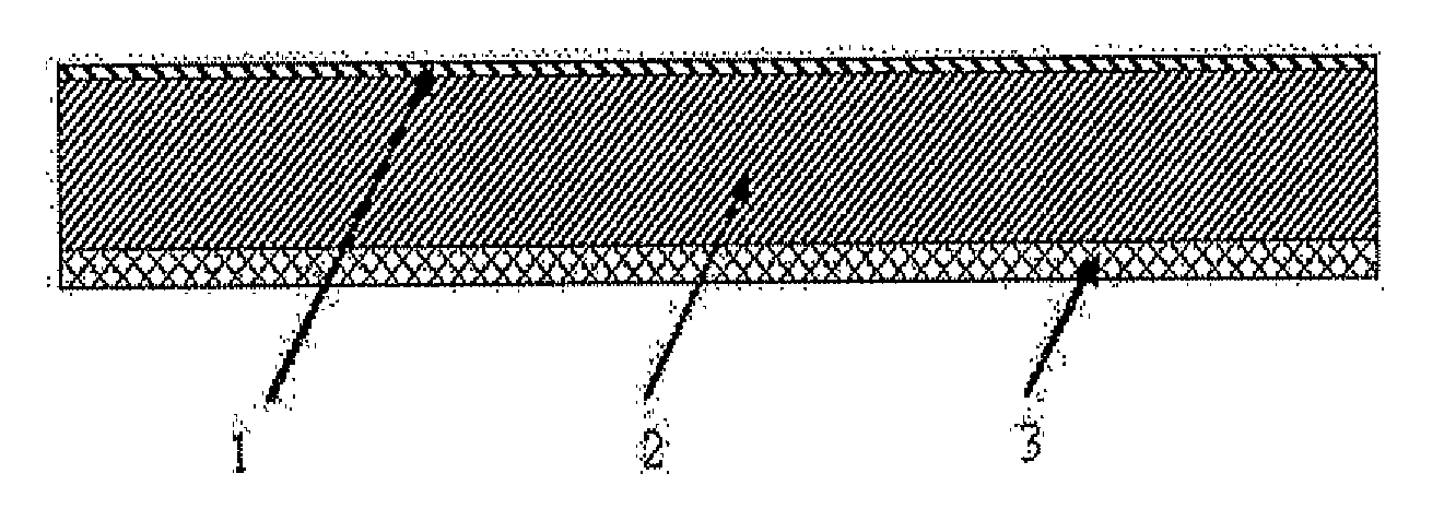
[0021](1) Onto one side of silicon substrate 2, Ti / Pd / Ag metal layers were evaporation uniformly successively, and used as the back electrode 3 of the carbon nanotube film solar cell, which was then led out by a wire;[0022](2) After purification, the double walled carbon nanotube in the form of aggregation was placed into deionized water, onto which ethanol solution was further added, then the double walled carbon nanotube spread into a film having a thickness of 100 nm;[0023](3) The spread double walled carbon nanotube film was transferred to the other side of silicon substrate 2 on which back electrode 3 was not prepared;[0024](4) The double walled carbon nanotube film was dried under infrared lamp, so that the double walled carbon nanotube film contacted with silicon substrate tightly. The double walled carbon nanotube film was taken as the upper electrode of the solar cell, which was then led out by a wire.

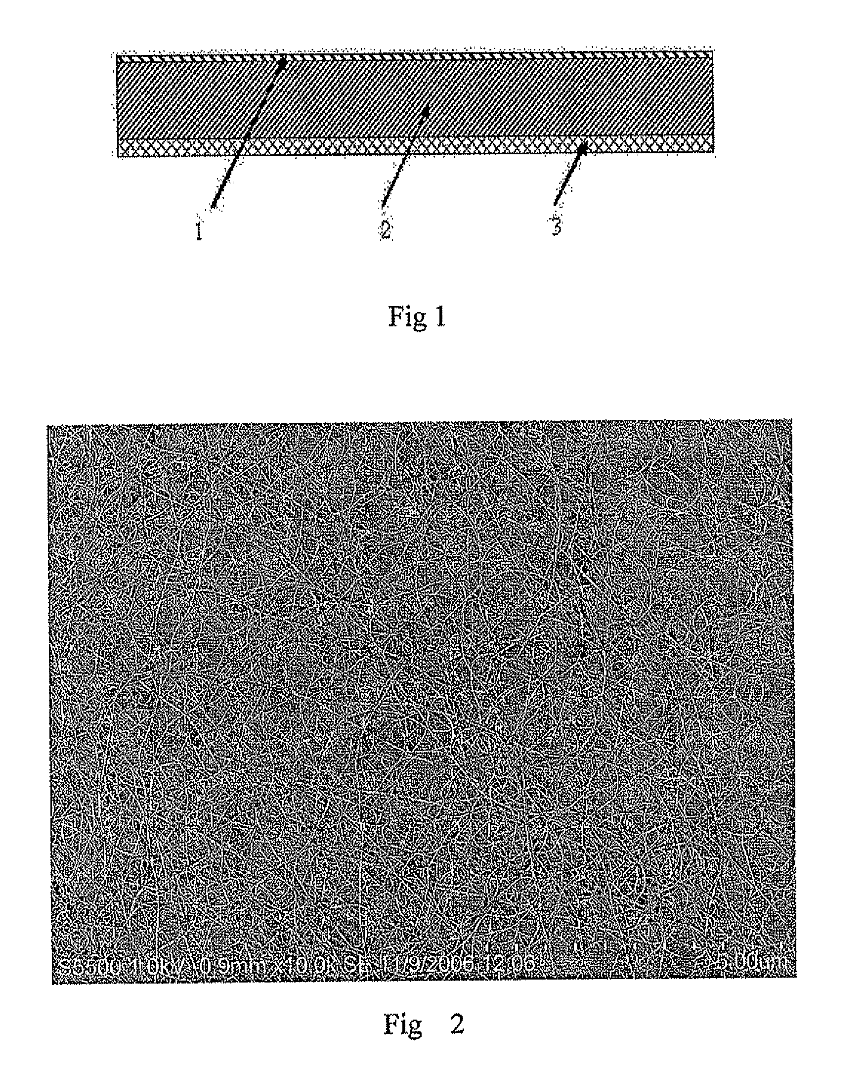
[0025]It could be seen from FIG. 2 that the thus prepared carbon nanotube...

example 2

[0027](1) Onto one side of silicon substrate 2, Ti / Au metal layers were evaporation plated successively, and used as the back electrode 3 of the carbon nanotube film solar cell, It was led out by a wire;[0028](2) After purification, the single walled carbon nanotube in the form of aggregation was placed into deionized water, onto which acetone solution was further added, then the single walled carbon nanotube spread into a film having a thickness of 50 nm;[0029](3) The spread single walled carbon nanotube film was transferred to the other surface of silicon substrate 2 on which back electrode 3 was not prepared;[0030](4) The combined body of the obtained single walled carbon nanotube film obtained in step (3) and silicon substrate in a drying oven, the temperature of which was kept under 50° C. for 3 hours, so that the single walled carbon nanotube film contacted with silicon substrate tightly. The single walled carbon nanotube film was taken as the upper electrode of the solar cell...

example 3

[0032](1) Onto one side of silicon substrate 2, Ti / Pd / Ag metal layers were evaporation plated successively, and used as the back electrode 3 of the carbon nanotube film solar cell. Then it was led out by a wire;[0033](2) The thus prepared aligned carbon nanotube was ultrasonic treated for 1 hour, so that it was dispersed thoroughly;[0034](3) The spread single walled carbon nanotube film was transferred to the other surface of silicon substrate 2 on which back electrode 3 was not prepared, obtaining a carbon nanotube film 1 having a thickness of 200 nm;[0035](4) The carbon nanotube film 1 was dried under infrared lamp, so that the carbon nanotube film 1 contacted with silicon substrate tightly. The carbon nanotube film was taken as the upper electrode of the solar cell. Then led it out by a wire.

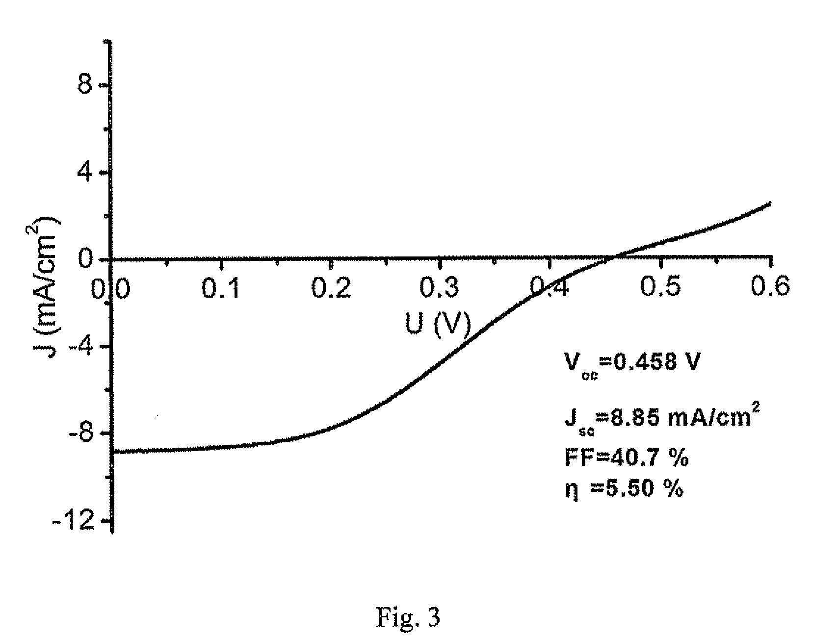
[0036]Solar cell conversion efficiency measurement was taken under irradiation of solar energy stimulator having an intensity of 30 mW / cm2, and the conversion efficiency obtained was 3.5%.


PUM

PropertyMeasurementUnit
thicknessaaaaaaaaaa
axial resistivityaaaaaaaaaa
short circuit currentaaaaaaaaaa

Abstract

A carbon nanotube-based solar cell and fabricating method thereof are provided. The method is achieved by applying carbon nanotube film (1) photoelectric conversion material and an upper electrode simultaneously. The method improves photoelectric conversion efficiency and life time of the solar cell, the fabricating method of the solar cell is simple, and the fabricating cost is low.

Description

TECHNICAL FIELD[0001]The present invention relates to a solar cell and a process for manufacturing the same. More specifically, the present invention relates to a solar cell taking carbon nanotube film as a photoelectric conversion material, and also a process for manufacturing the same.BACKGROUND[0002]Currently, solar energy is the cleanest energy source, which could almost be utilized endlessly. As far as we know, the solar energy received by globe per 40 seconds is equal to those contained in 21 billion barrels of petroleum, corresponding to the sum of those consumed a whole day on the earth. The utilization of solar energy includes the conversion of sunlight energy to heat, sunlight energy to electricity, and sunlight energy to chemical energy. Solar cell is a typical example for converting sunlight energy to electricity (which is also known as photoelectric conversion); and it is based on photovoltaic effect of semiconductor material. According to the types of the photoelectric...

Claims


Application Information

Patent Timeline
Patent Type & Authority Applications(United States)
IPC IPC(8): H01L31/00H01L31/18
CPCB82Y10/00H01L31/022466H01L31/035281H01L31/072Y02E10/549H01L51/0048H01L51/4253H01L51/444H01L31/1884Y02P70/50H10K85/221H10K30/821H10K30/30
Inventor JIA, YIWEI, JINQUANSHU, QINKEWANG, KUNLINZHUANG, DAMINGZHANG, GONGLIU, WENJINLUO, JIANBINWANG, ZHICHENGWU, DEHAI
Owner TSINGHUA UNIV
Why Eureka
Try Eureka