Method of forming a protective film for a magnetic recording medium, a protective film formed by the method and a magnetic recording medium having the protective film
a technology of magnetic recording medium and protective film, which is applied in the direction of magnetic layer protection, record information storage, instruments, etc., can solve the problems of insufficient adhesion suppression, a-c film, thickness problem, etc., and achieve good adhesion, good durability and corrosion resistance, and sufficient suppression of adhesion of contamination gases
- Summary
- Abstract
- Description
- Claims
- Application Information
AI Technical Summary
Benefits of technology
Problems solved by technology
Method used
Image
Examples
example 1
[0039]A metallic film layer was formed on an aluminum substrate with a diameter of 95 mm and a thickness of 1.75 mm by sequentially depositing an underlayer of CoZrNb 40 nm thick, an intermediate layer of ruthenium 15 nm thick, and a magnetic recording layer of CoCrPt—SiO2 15 nm thick.
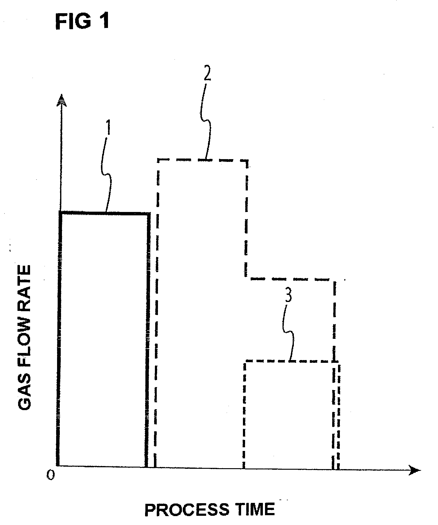
[0040]The obtained lamination was installed in a deposition chamber of a filament type plasma CVD device. Ethylene gas was introduced into the deposition chamber at a flow rate of 40 sccm. A dc power was supplied at 180 V between a cathode filament and an anode, and ethylene plasma was generated by emission of thermal electrons from the cathode filament. The pressure in the deposition chamber was 0.53 Pa. A bias voltage at −120 (relative to the ground potential) was applied on the lamination to deposit a DLC film. Adjusting the deposition time, a DLC film was formed to a thickness of 3.0 nm.
[0041]After completion of DLC film deposition, argon gas was introduced at a flow rate of 50 sccm substituting fo...
example 2
[0044]A sample of Example 2 was obtained in the same manner as in Example 1 except that the gas for the nitrogen plasma treatment was changed from the mixture gas of argon gas at a flow rate of 30 sccm and nitrogen gas at a flow rate of 20 sccm, to nitrogen gas at a flow rate of 30 sccm.
[0045]The obtained sample was exposed to the SO2-containing test gas in the same conditions as in Example 1. An amount of SO2 gas adhered on the sample of Example 2 was 0.85 ng / cm2, which was again a satisfactory value.
[0046]On the obtained DLC film (a protective film) of the sample, liquid lubricant of perfluoropolyether was applied by the dip-coating method, to form a lubricant film. The lubricant film had a sufficient thickness of 1.2 nm (which was measured by the infrared (IR) spectroscopy), and the bonding characteristic between the DLC film (a protective film), and the lubricant film was satisfactory.
example 3
[0047]The same procedure as in Example 1 was conducted including formation of a metallic film layer on an aluminum substrate, formation of a DLC film, and argon plasma treatment.
[0048]After the argon plasma treatment, the resulted lamination was moved to another separate filament type plasma CVD device, in which nitrogen plasma treatment was conducted in a mixture gas of argon gas at a flow rate of 30 sccm and nitrogen gas at a flow rate of 20 sccm in the same plasma generating conditions as in Example 1 for 1.0 sec to obtain a sample of Example 3.
[0049]The obtained sample was exposed to the SO2-containing test gas in the same conditions as in Example 1. An amount of SO2 gas adhered on the sample of Example 3 was 0.75 ng / cm2, which was yet satisfactory value.
[0050]On the DLC film (a protective film) of the obtained sample, liquid lubricant of perfluoropolyether was applied by a dip-coating method to obtain a lubricant film. The lubricant film had a sufficient thickness of 1.2 nm (wh...
PUM
| Property | Measurement | Unit |
|---|---|---|
| thickness | aaaaa | aaaaa |
| thickness | aaaaa | aaaaa |
| thickness | aaaaa | aaaaa |
Abstract
Description
Claims
Application Information
 - R&D
- Intellectual Property
- Life Sciences
- Materials
- Tech Scout
- Unparalleled Data Quality
- Higher Quality Content
- 60% Fewer Hallucinations
Browse by: Latest US Patents, China's latest patents, Technical Efficacy Thesaurus, Application Domain, Technology Topic, Popular Technical Reports.
© 2025 PatSnap. All rights reserved.Legal|Privacy policy|Modern Slavery Act Transparency Statement|Sitemap|About US| Contact US: help@patsnap.com

