
Apparatus and method for detection, location, and identification of gamma sources

Inactive Publication Date: 2010-07-01
SPACE MICRO A CORP OF DELAWARE
View PDF5 Cites 14 Cited by
  • Summary
  • Abstract
  • Description
  • Claims
  • Application Information

AI Technical Summary

Benefits of technology

[0010]In one form, each of the scintillation crystals has a length to diameter ratio equal to or greater than about 2:1. In some embodiments, axes of the scintillation crystals are equiangularly disposed. In some embodiments, the scintillation crystals comprise cerium-doped lanthanum bromide. In some embodiments, it is preferred to use each scintillation crystal having a minimum resolution. One measure of a suitable resolution is a full width at half maximum (FWHM) energy resolution of less than 4% at 660 KeV to discriminate against scattered radiation. In some embodiments, each scintillation crystal comprises at least one end cap and at least one trim shield mounted parallel to the end cap to enhance anisotropic response by increasing variability at detection null points.
[0024]Generally, an isotope locating system is disclosed utilizing a gamma ray detection. Additionally, electrical signals produced in response to gamma ray detection may be used for isotope identification and improving resolution in isotope identification. In some embodiments, these are based on an ensemble comprising of two or more geometrically configured sensors, which may use of small trim shielding components. Together, the sensors may enable the simultaneous identification and determination of the azimuth of one or more gamma ray sources over a 360° field of view. The response of each sensor element may be anisotropic, providing a response dependent on the azimuth of the source relative to the sensor, while the integrated response of the ensemble is isotropic, providing a reference for azimuth determination and detector sensitivity. The optional use of extremely high energy resolution scintillation sensors enables determination of gamma photons directly from the source, and discrimination of these photos from scattered photons and background radiation without the losses associated with collimated shielding. An improved algorithm accounting for low level scintillator emissions may be used to improve the ability to provide the azimuth of the isotopes of interest over a wide range of environmental conditions. The system may be utilized in mobile search modes including robotic applications as well as fixed incident response modes.
[0027]The presently disclosed subject matter enables the use scintillation crystals which may be used at room temperature for gamma and x-ray detection. This is in contrast to high purity germanium crystals which must be cooled to cryogenic temperatures. Gaseous ion chambers which can operate at room temperature do not have the density and thus the sensitivity of scintillators. The most important radiation measurement characteristics of merit for a scintillation crystal sensor applied to gamma source detection, identification and location are high density to provide sensitivity and high light yield to provide precise energy resolution for identifying photo peaks of specific radioisotopes. Other characteristics such as shock resistance, resistance to hydroscopic damage and temperature stability are also important to develop a useful field instrument for reliable operation outside of the laboratory.

Problems solved by technology

The United States government has identified a vital need of law enforcement, first responder and military staff responsible for detecting and responding to radiological threats to the United States to advance the state of the art of available omni-directional radiation detection devices, such as radiation portals and hand-held devices which are sensitive enough to detect many threats, but lack the capability to rapidly determine the location of the radiation source.
This problem is complicated by the fact that the terrestrial environment of concern includes significant naturally occurring radioactive material (NORM) and legitimate medical and industrial sources, which camouflage a threat source.
Additionally the threat source will often be present in a scatter rich environment further masking the direction and energy of the source.
The current information provided may be ambiguous and inadequate in both routine inspection and live threat response scenarios given that the main goal is to find the radiation source or sources quickly to determine the risk level and the appropriate response.
Still other devices, known as Compton cameras, while capable of gamma ray azimuth detection, cannot meet the above requirements.
However, Compton cameras currently are laboratory devices too large and cumbersome for use as set forth above.

Method used


Image

  • Apparatus and method for detection, location, and identification of gamma sources
  • Apparatus and method for detection, location, and identification of gamma sources
  • Apparatus and method for detection, location, and identification of gamma sources

Examples


Embodiment Construction

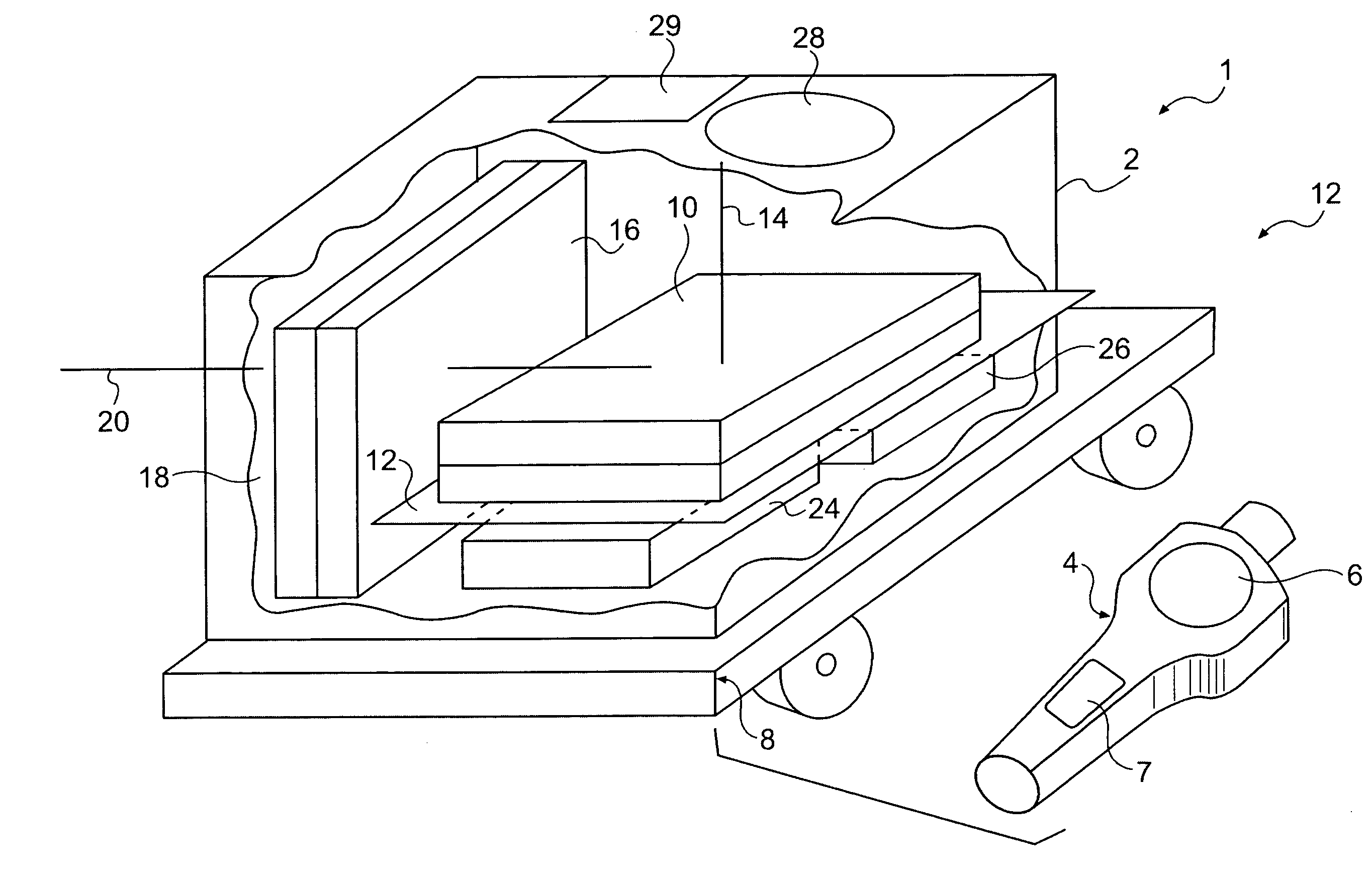
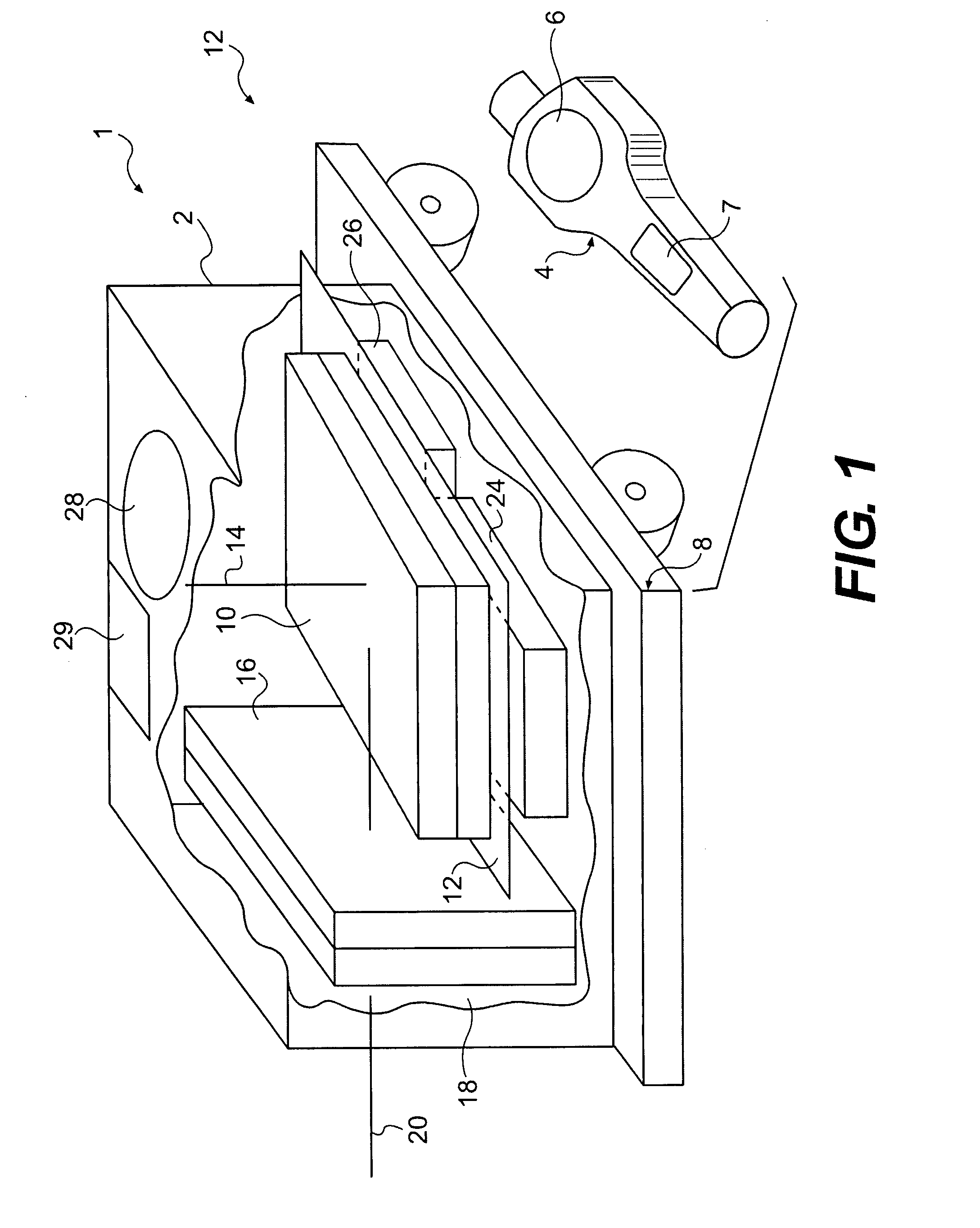
[0038]FIG. 1 is a prospective illustration of a detector instrument 1 constructed in accordance with an embodiment of the present invention. In one form, the detector instrument 1 will detect azimuth of a gamma radiation source. In a further embodiment, both azimuth and elevation may be determined in order to provide a three dimensional representation of location of the gamma source. Additionally, as further described below, energy spectra signatures of sources may be resolved in order to identify one or more radiation sources. The detector instrument 1 may be self-contained in a housing 2. Optionally, the detector instrument 1 may further comprise a remote control unit 4. In the present illustration, the remote control unit 4 comprises a display 6 and a user interface 7. The user interface 7 may comprise switches and other control means. Commonly, the remote control unit 4 will communicate with the housing 2 by a radio frequency (RF) link. Other or additional forms of communication...


PUM


Abstract

An apparatus for detecting and determining a source azimuth for gamma radiation includes at least two scintillation crystals at angular offsets and directed toward a common plane of detection, photodetectors adjacent to each of the scintillation crystals for converting the light response of the scintillation crystals into distinct electrical signals, and a digital processing system configured to analyze spectral data from each electrical signal produced for each crystal. The digital processing system monitors a finite number of spectral windows corresponding to a selected set of radioisotopes, and uses one or more of the electrical signals to determine a signal intensity and a likely source azimuth for a detected radioisotope in the plane of detection. Another scintillation crystal directed outside of the common plane of detection may be used for three-dimensional detection. Related methods for detection and location of gamma ray sources are discussed.

Description

CROSS-REFERENCE TO RELATED APPLICATIONS[0001]This application claims the benefit of U.S. Provisional Patent Application No. 60 / 812,894 filed Jun. 13, 2006, the contents of which are hereby incorporated by reference in their entirety.STATEMENT REGARDING FEDERALLY SPONSORED RESEARCH OR DEVELOPMENT[0002]The captioned invention was developed under United States of America Department of Defense Small Business Innovation Research contract NBCHC060045.BACKGROUND OF THE INVENTION[0003]1. Field of the Invention[0004]The present subject matter relates generally to radiation detection devices, and in particular to compact scintillation radiation detector ensembles that enable detection, identification and azimuth location of a radiation source in a single embodiment.[0005]2. Related Art[0006]The United States government has identified a vital need of law enforcement, first responder and military staff responsible for detecting and responding to radiological threats to the United States to adva...

Claims


Application Information

Patent Timeline
IPC IPC(8): G06F19/00G01T1/202G01T7/00
CPCG01T1/20G01V5/0075G01V5/26
Inventor WINSO, JAMES H.FENNELL, MICHAEL D.
Owner SPACE MICRO A CORP OF DELAWARE
Learn More