Permeation method and apparatus for preparing fluids containing high purity chlorine dioxide

a technology of chlorine dioxide and permeation method, which is applied in the direction of inorganic chemistry, gas generation devices, membranes, etc., can solve the problems of affecting the health of people, affecting the operation of reactors, and achieving critical concentrations that are more difficult to achieve, so as to facilitate the construction of reactors and simple equipment

Active Publication Date: 2010-07-29
NOSZTICZIUS ZOLTAN
View PDF19 Cites 20 Cited by
  • Summary
  • Abstract
  • Description
  • Claims
  • Application Information

AI Technical Summary

Benefits of technology

[0042]In these permeation reactors we can apply even such corrosive reagents like hydrochloric acid for example (which is better than other acids regarding the ClO2 yield and the rate of the reaction) without contaminating the target medium with these reagents. The reagents can be fed into the reactor in the form of aqueous solutions or can be placed there in the form of reagent containing hydrogels. As the permeable wall separates the reagents from the target medium they cannot be mixed and the target medium will not be diluted, thus the conversion can approach the theoretical maximum. A further advantage is that a ClO2 “puff” can be avoided even at higher reagent concentrations because chlorine dioxide is formed in a liquid phase (where a “puff” can occur less easily) then permeates rapidly into the target fluid where its concentration is much lower. It is a major advantage that the production of a clean chlorine dioxide does not require its evaporation, and that its permeation is driven by a natural concentration gradient, as this way the process does not need energy input and requires a relatively simple equipment only.
[0043]The invention presents such reactors coupled with permeation. The reactors differ from each other depending on the ultimate purpose of the ClO2 usage. Some of the embodiments presented here are aiming the production of small amounts of chlorine dioxide and are simple batch reactors because these constructions can be satisfactory in many applications. Some important advantages of the permeation technique can be realized, however, in continuously working tubular reactors only, where e.g. a close to ideal conversion can be achieved by recirculation of the partially exhausted reagents. A further advantage of the silicon rubber material is, that this material is commercially available in the form of various tubings and sheets, moreover oligomeric pastes and glues are also available which can be polymerized to various forms. All of these facilitate the construction of reactors with variable forms.

Problems solved by technology

However, applying such large quantities of an antimicrobial agent is costly, moreover these agents should be removed by rinsing after the disinfection, which causes further complications and costs.
When applying e.g. chlorine gas as a disinfectant in a contaminated environment achieving the critical concentration is more difficult, as chlorine reacts with various organic compounds.
This is a problem not only because in such a case disinfection requires much more chlorine but the chlorinated compounds produced this way can be harmful to the human health (e.g. some chlorinated hydrocarbons are well known carcinogens).
It is a major obstacle for the rapid spread of various chlorine dioxide applications that the gas has to be generated on the spot of the utilization.
This is because chlorine dioxide—unlike chlorine—cannot be stored in gas cylinders and consequently cannot be transported in such a form, as pure gaseous chlorine dioxide or any gaseous mixture containing more than 10% (especially between 25 and 30% (volume / volume)) chlorine dioxide can decompose rapidly.
While such a puff can be easily avoided with due care, this does not modify the fact that chlorine dioxide cannot be stored in gas cylinders thus it has to be generated on the spot anyway.
While among the possible starting materials of the chlorine dioxide synthesis it is the chlorate which is the least expensive one, such a technology can be applied economically only when the chlorine dioxide demand is at least several tons per day because of the expensive equipment.
Various other applications require only smaller amounts of chlorine dioxide and the use of generators is not economic in such cases.
This means on one side that the final product will be contaminated by chlorate and on the other side that the maximum yield of chlorine dioxide is limited to 62.5% compared to the optimum stoichiometry with hydrochloric acid.
The chlorine dioxide solution produced with this method is corrosive, however, because of its acidic pH and its chloride ion content.
It is a disadvantage of the method described in the previous paragraph that the ClO2 solution produced this way also contains some non-reacted NaClO2, citric acid, sodium citrate, NaClO3, and NaCl.
Such a contamination is always a problem especially if the aim is to produce a more concentrated ClO2 solution because in that case the concentration of the contaminating components would be also higher in the final solution.
A main disadvantage of this method—beside a low level contamination of the final product caused by small droplets traveling with the stripping gas—is the need for stripping and absorbing towers, that these devices should be operated with recirculation, moreover that to reach a higher efficiency two stripping and two absorption towers should be connected in series.
When the pellet is placed into water, however, the components start to dissolve and react with each other.
It cannot be avoided, however, that the solution be contaminated by more or less sodium hydrogen sulfate or calcium chloride (depending on which component was applied in an excess) and also with some unreacted chlorite.
Moreover the end-product chloride ions—together with sodium or hydrogen counter ions—also diffuse out of the pores of the tablet and contaminate the solution.
While the reagent concentrations are rather high within the sachet the conversion is still far from complete.
It is a common disadvantage of the methods applying either pellets or sachets that the aqueous chlorine dioxide solution produced by these methods will be contaminated by other materials as well.
Another drawback of these methods is that because of the gradual dissolution and dilution of the reagents even the 62.5% yield cannot be achieved and to reach even a low final yield requires longer waiting periods.
Finally it is also a problem that the exhausted tablets and envelopes form a waste which should be handled in some way.
A common problem of these constructions that the rate of the chlorine dioxide evolution cannot be controlled after starting the reaction, moreover, this rate may depend on the reaction time and the humidity of the air as well.
Thus to construct a generator maintaining a constant chlorine dioxide level in a continuous air stream with the aforementioned envelopes or sachets would be a very difficult task, at least.
A common serious problem of all known methods is the separation of the product from the starting materials.
There is either no separation, or the separation is not perfect or it is an equipment and energy demanding process.
This equipment and energy consuming separation procedure increases the costs of the production, thus it is often skipped (e.g. WO 2006 / 062456).
In that case, however, the produced ClO2 solution is contaminated by a mixture of various salts and acids, and residual reducing agent.
The aqueous chlorine dioxide solution produced this way, however, is contaminated by the end product NaCl and some unreacted chlorine or NaClO2.
The procedure, which combines the electrochemical oxidation of chlorite with the pervaporation of chlorine dioxide (U.S. Pat. No. 4,683,039) cannot provide a chlorine dioxide solution which is entirely free of contaminants either, in spite of the expensive porous membrane applied in that procedure.
The yield of this reaction can approach the theoretical maximum of 4 ClO2 produced from 5 NaClO2 only in the case of hydrochloric acid, the corrosive properties of which, however, limit its use.
Nevertheless it is a common problem of all these methods that the ClO2 yield is lower in the case of organic acids and usually they are not able to reach even this lower limit either.
Moreover, contamination is also a problem here and to get rid of these contaminants requires costly equipments and time and energy consuming procedures (see e.g. WO 2006 / 020704).
A common drawback of these methods is, however, that after activating such a gaseous chlorine dioxide producing device it is difficult or impossible to control the rate of the ClO2 production.
Further, gaseous ClO2 is more difficult to handle, consequently the application of gaseous products is rather limited compared to ClO2 containing solutions.

Method used


Image

  • Permeation method and apparatus for preparing fluids containing high purity chlorine dioxide
  • Permeation method and apparatus for preparing fluids containing high purity chlorine dioxide
  • Permeation method and apparatus for preparing fluids containing high purity chlorine dioxide

Examples


example 1

Tubular Reactor with Permeable Walls and a Batch Method to Prepare Aqueous Chlorine Dioxide Solution

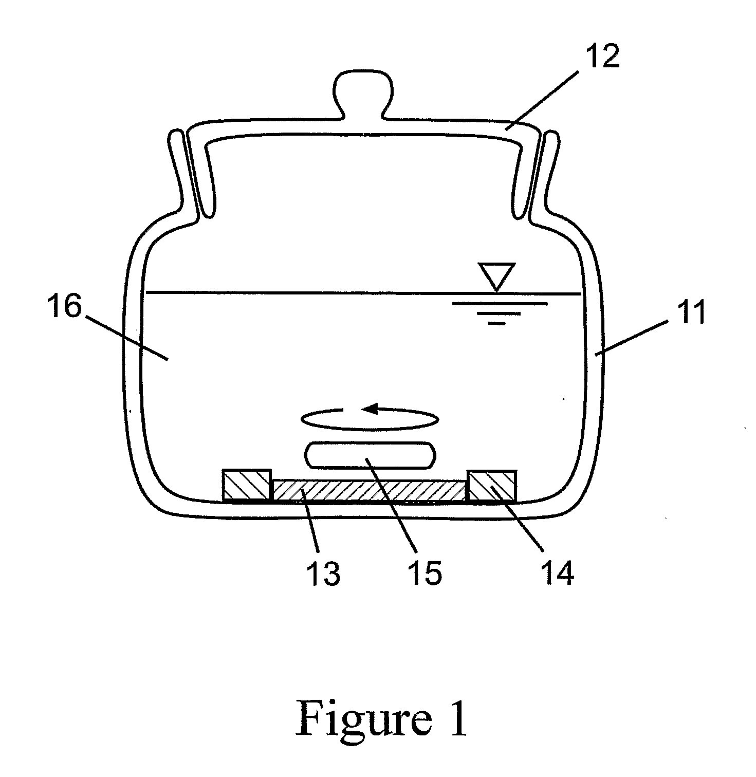
[0129]According to this method the reactor shown on FIG. 3a) can be filled up e.g. with the double syringe shown on FIG. 3b). Syringe 35 containing the NaClO2 solution and syringe 36 containing the acidic solution were inserted into device 37 only after filling them with the reagents. The two solutions can be pushed simultaneously with the device shown on FIG. 3b) into the silicon rubber tube 31 with a length of 7 m, inner diameter 1 mm, outer diameter 2 mm. While flowing in, the reagents are mixed at the beginning of the common tube section 38. After filling it up, the two ends of the silicon rubber tube were closed with a PVC tube section 32. The silicon rubber tube was immersed into the glass bottle 33 containing 0.5 l distilled water as shown on FIG. 3a). The water was stirred with a magnetic stirrer bar 34. The chlorine dioxide evolving inside the silicon rubber tube permeated in...

example 2

Countercurrent Tubular Reactor with Permeable Walls and a Continuous Method to Produce Chlorine Dioxide—Containing Gas or Water Streams

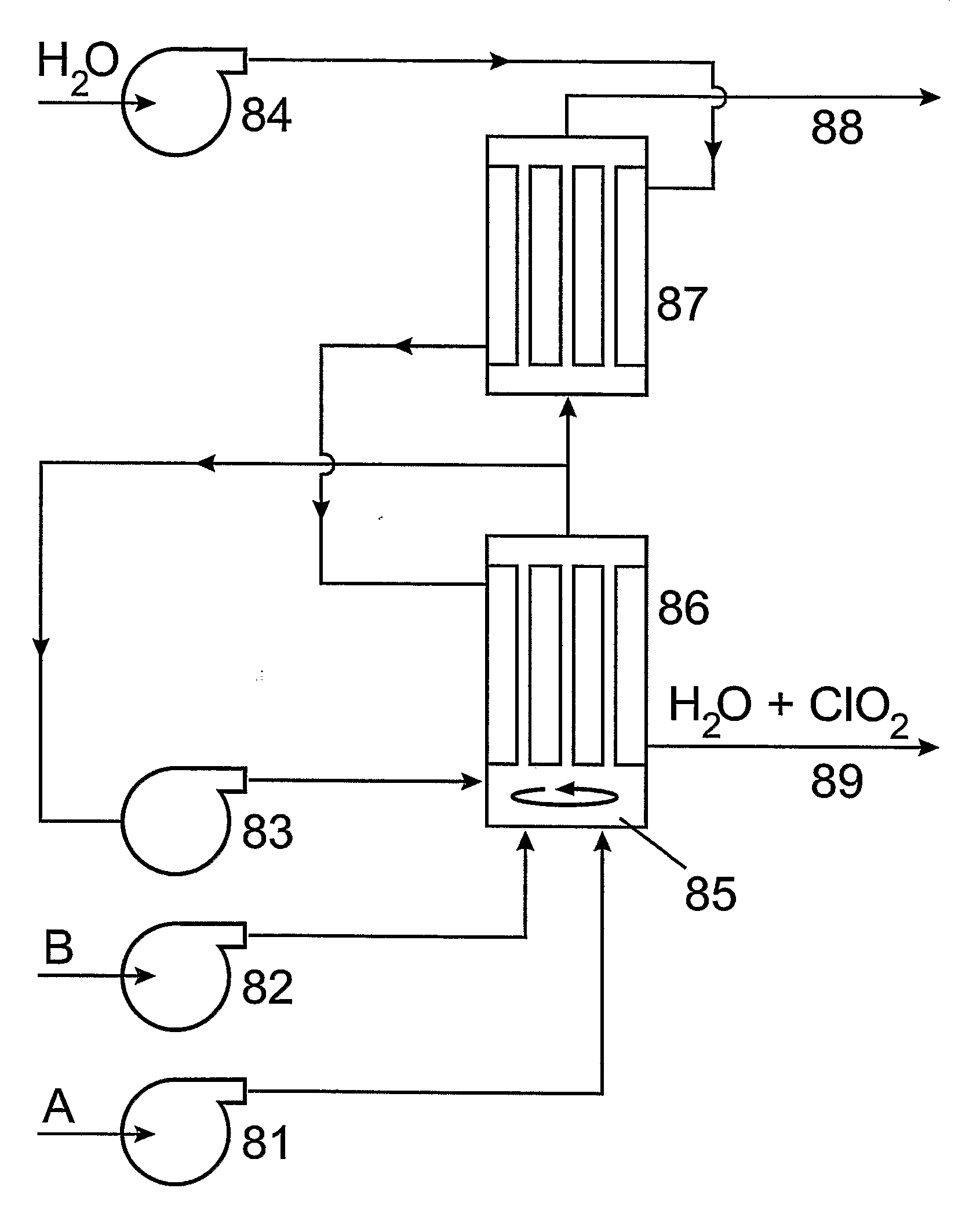
[0153]The device can be designed based on point D) of Example 1. (henceforth: Experiment D)). As shown in FIG. 5. the two solutions are pumped by two peristaltic pumps 51 and 52 continuously into the core of the silicon rubber tube 53 around which water or air is kept flowing by pump 54. The endproduct—the fluid (water or air) saturated with ClO2—leaves the reactor at vent 55 while the exhausted reagents are collected in tank 56. The silicon rubber permeation reactor 53 has a length of 7 m, inner diameter 1 mm and outer diameter 2 mm. (This is the same tube that was applied in Experiment D).) As, according to our experiments, the time needed to reach maximal conversion is at least 12 min and the inner cubic capacity of the tube is 5.5 cm3, the maximum value of the flow rate in the tube can be 0.46 cm3 / min. This means that both solution I. (an aqueous...

example 3

A Micro-Reactor Applying a Flat Silicone Rubber Membrane and Hydrogel Embedded Reagents to Establish a Slow Focused Chlorine Dioxide Input of Small Quanta

[0155]In examples 1. and 2. we have presented devices which can be used for the production of chlorine dioxide-containing water or air. These fluids containing pure chlorine dioxide can be used to flood places where we need e.g. the biocid effect of chlorine dioxide. Anyway, it can happen that we want to apply chlorine dioxide not in a great quantity, homogeneously spread in a big space but only in minute quantities, focussed on a limited area. In this case our intention is to construct a disposable, small reactor which can be used also by a non-professional person easily, without any risk. FIG. 6. shows such a micro-reactor.

[0156]FIG. 6.a) shows the cross-sectional view of the micro-reactor. The bottom of the reactor is the disk 61 made of a textile reinforced silicon rubber membrane with a thickness of 0.3 mm and diameter of 18 m...


PUM

PropertyMeasurementUnit
thicknessaaaaaaaaaa
distribution coefficientaaaaaaaaaa
molar ratioaaaaaaaaaa

Abstract

Method to prepare fluids (liquids and gases) containing pure chlorine dioxide which is not contaminated by the starting materials or the byproducts of the chlorine dioxide synthesis or to deliver pure chlorine dioxide into any medium capable of dissolving chlorine dioxide, wherein the chlorine dioxide generated in the process is transported across a pore free polymeric membrane via selective permeation into the target medium. Apparatus to realize the said method, wherein the generation of chlorine dioxide is carried out in such a reactor where some or all walls comprising the reactor, or the walls of a permeator unit attached to the reactor, are made of the said pore free polymer, characteristically some kind of silicone rubber, which is highly permeable to chlorine dioxide, but which is practically impermeable for the acidic and corrosive reagents used for the chlorine dioxide synthesis, its permeability being at least 3 orders of magnitude lower for these contaminating components compared to that of chlorine dioxide. The invention can be realized both by batch and by continuous reactors.

Description

TECHNICAL FIELD[0001]The object of the invention is a method to prepare fluids (i.e. liquids and gases) containing pure chlorine dioxide which is not contaminated by the starting materials or the byproducts of the chlorine dioxide synthesis or to deliver pure chlorine dioxide into any fluid target medium capable of dissolving chlorine dioxide, wherein the chlorine dioxide generated in the process is transported across a pore free polymeric membrane via selective permeation into the fluid target medium. The invention also relates to different apparatus to realize said method.BACKGROUND OF THE INVENTIONUse of Chlorine Dioxide: Ideal Biocide and Bleaching Agent[0002]Chlorine dioxide is a very effective biocide. According to the Annual Research Report, Southwest Research Institute, San Antonio, Tex., 1996, “Chlorine dioxide is a powerful biocide that can kill fungus, bacteria, and viruses at levels of 0.1 to 1 part per million in contact times of a few minutes.” Chlorine dioxide is also...

Claims


Application Information

Patent Timeline
Patent Type & Authority Applications(United States)
IPC IPC(8): C01B11/02C25B1/26B01J19/00
CPCB01D63/087B01D69/02B01D71/70B01D2325/02C01B11/028B01J19/245B01J19/2475C01B11/024C01B11/026B01D2325/20
Inventor NOSZTICZIUS, ZOLTANBALOGH, SANDORGYOKERNE WITTMANN, MARIAKALY-KULLAI, KRISTOFMEGYESI, MARIANNAVOLFORD, ANDRASMERKERTNE BALOGH, EMESEBALOGH, LEVENTE
Owner NOSZTICZIUS ZOLTAN
Why Eureka
Try Eureka