Environmentally robust disc resonator gyroscope

a disc resonator and gyroscope technology, applied in the field of gyroscopes, can solve the problems of sensing errors and drift, large and heavy, and the mechanism of older conventional mechanical gyroscopes is very heavy, so as to reduce the sensitivity to external thermal and mechanical stress, improve reliability, and reduce manufacturing costs

Active Publication Date: 2010-10-07
THE BOEING CO
View PDF11 Cites 61 Cited by
  • Summary
  • Abstract
  • Description
  • Claims
  • Application Information

AI Technical Summary

Benefits of technology

[0019]Micromachined disc resonator gyroscopes (DRGs) are disclosed designed to be virtually immune to external temperature and stress effects. The DRG is a vibratory gyroscope that measures angular rate which is designed to have reduced sensitivity to external thermal and mechanical stress. The DRG features an integrated isolator that may be fabricated on the same wafer as the electrode wafer forming a plurality of integrated isolator beams. In addition, the DRG may include a wafer level hermetical vacuum sea

Problems solved by technology

Older conventional mechanical gyroscopes were very heavy mechanisms by current standards, employing relatively large spinning masses.
Currently this is often performed with expensive conventional spinning mass gyros (e.g., a Kearfott inertial reference unit) or conventionally-machined vibratory gyroscopes (e.g. a Litton hemispherical resonator gyroscope inertial reference unit).
However, both of these are very expensive, large and heavy.
This transfer or coupling admits external disturbances and energy loss indistinguishable from inertial rate input and hence leads to sensing errors and drift.
Other planar tuning fork gyroscopes may achieve a degree of isolation of the vibration from the baseplate, however these gyroscopes lack the vibrational symmetry desirable for tuned operation.
However, these designs are not suitable for or have significant limitations with thin planar silicon microfabrication.
However its high aspect ratio and 3D curved geometry is unsuitable for inexpensive thin planar silicon microfabrication.
Moreover, the case for this gyroscope is not of the same material as the resonator proof ma

Method used


Image

  • Environmentally robust disc resonator gyroscope
  • Environmentally robust disc resonator gyroscope
  • Environmentally robust disc resonator gyroscope

Examples


Embodiment Construction

[0050]1. Overview

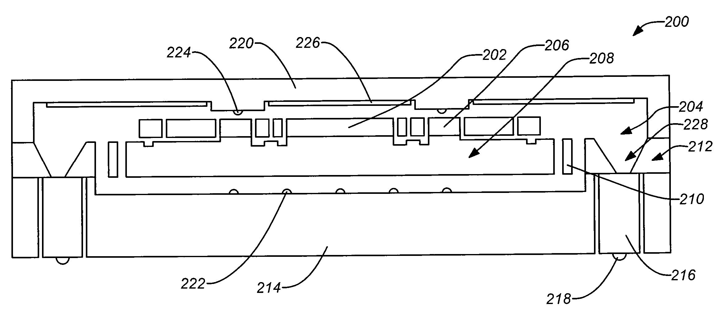
[0051]Sensitive elements (resonator, electrode) are completely suspended by long flexible beams, thus isolating them from external stress and thermal effects. The isolator beams may be weak and flexible to tolerate large displacements with very little resistance. Therefore, any stress or distortion to the die casing, due to either CTE mismatch or external stress, can be absorbed by the isolator beams and will not be transmitted to the sensing elements. The isolator beams are fabricated by etching the same wafer as the electrodes (the electrode wafer), thus minimizing CTE mismatch and reducing complexity and cost. Beam rigidity of the isolator beams may be custom designed to provide attenuation to vibration of particular frequency range(s). Silicon vertical feedthrough can eliminate potential vacuum leakage paths, and reduces CTE mismatch caused by metals.

[0052]In further embodiments, employing flip-chip ball grid array (BGA) can allow direct attachment of the dies t...


PUM

PropertyMeasurementUnit
Electrical conductoraaaaaaaaaa
Vacuumaaaaaaaaaa

Abstract

Micromachined disc resonator gyroscopes (DRGs) are disclosed designed to be virtually immune to external temperature and stress effects. The DRG is a vibratory gyroscope that measures angular rate which is designed to have reduced sensitivity to external thermal and mechanical stress. The DRG features an integrated isolator that may be fabricated on the same wafer as the electrode wafer forming a plurality of integrated isolator beams. In addition, the DRG may include a wafer level hermetical vacuum seal, flip chip ball grid array (BGA), and vertical electrical feedthrough to improve reliability and to reduce manufacturing cost. An additional carrier layer may be used with shock stops, vertical electrical feedthrough, and the flip chip BGA. A pyrex or quartz cap with embedded getter and shock stops can be employed.

Description

CROSS-REFERENCE TO RELATED APPLICATIONS[0001]This application is related to the following co-pending applications, which are all incorporated by reference herein:[0002]U.S. patent application Ser. No. ______, filed on this same day herewith, and entitled “ISOLATED ACTIVE TEMPERATURE REGULATOR FOR VACUUM PACKAGING OF A DISC RESONATOR GYROSCOPE”, by Ge et al. (Attorney Docket Number 08-0831 / BOECP060);[0003]U.S. patent application Ser. No. 11 / 458,911, filed Jul. 20, 2006, and entitled “DISC RESONATOR GYROSCOPES”, by Kubena et al.;[0004]U.S. patent application Ser. No. 11 / 757,395 (Application Publication No. 2008-0295622A1), filed Jun. 4, 2007, and entitled “PLANAR RESONATOR GYROSCOPE WITH CENTRAL DIE ATTACHMENT”, by Challoner;[0005]U.S. patent application Ser. No. 11 / 615,872, filed Dec. 22, 2006, and entitled “VIBRATORY GYROSCOPE WITH PARASITIC MODE DAMPING”, by Whelan et al.; and[0006]U.S. patent application Ser. No. 11 / 831,822, filed Jul. 31, 2007, and entitled “DISC RESONATOR INTEGR...

Claims


Application Information

Patent Timeline
IPC IPC(8): G01C19/56B32B37/02
CPCY10T156/10G01C19/5684
Inventor GE, HOWARD H.CHALLONER, A. DORIAN
Owner THE BOEING CO
Why Eureka
Try Eureka