
Joint and joining method for plastic pipe

a multi-layer composite tubing and joining method technology, applied in the field of joining and joining methods of multi-layer composite tubing, can solve the problems of high capital cost of straight copper tubing and chlorinated polyvinyl chloride (cpvc), difficulty in bending pex and polybutylene tubing, and difficulty in preventing kinking and twisting in the tubing. , to achieve the effect of reducing the number of molded components

Inactive Publication Date: 2010-11-25
ORION ENTERPRISES
View PDF40 Cites 20 Cited by
  • Summary
  • Abstract
  • Description
  • Claims
  • Application Information

AI Technical Summary

Benefits of technology

[0010]The outer layer can be offered as a pigmented product with special additives such as UV inhibitors to protect against UV attack of the pipe (a problem inherent in PP materials without additives), since the outer layer is not a wetted component. Dissimilar systems such as PVDF-Aluminum-PP combinations can even be offered where PVDF is needed for the wetted contact layer, such as in a process piping application involving concentrated sulfuric acid (greater than 98% acid concentration), and PP can be used as the outer layer to reduce the price of the tubing and fittings. Such a system could be delivered into a project in long coils (e.g., 100 meter coils) and rolled out into seamless and jointless straight lengths. Further, a certain number of consecutive bends can be field-formed using forming and bending tools, and flexible inserts.
[0011]Advantageously, when using the multilayer composite tubing as the base for a cost effective water, air, or process piping system, the tubing ends can be field-formed into female sockets, as described for example in U.S. patent application Ser. No. 11 / 388,366 (since the malleable metallic substrate is formable in this fashion) and then joined using mating male parts of similar multilayer construction by means of direct or indirectly applied heat, induction heating or modified electrofusion. This would allow the metallic substrate to be completely isolated from the wetted fluid, while offering a proven, readily accepted joint and joining method. The use of malleable metals such as aluminum or copper serve a dual purpose in this instance in that they are formable, have better strength than straight thermoplastic materials, yet also are excellent conductors of heat and would thereby assist in the transmitting of heat between the male spigots and formed female sockets, yet would also resist thermal swelling of the plastic layers, resulting in strong welded joints.
[0012]The use of a flared socket into the tubing end that is mated to a male spigoted coupling or fitting capable of being heated by indirect application of heat or electrofusion is a novel and non-obvious method that solves many of the problems previously associated with such joints in straight thermoplastic rigid or flexible tubing, and in multilayer tubes. The joints can be easily and readily made by means of a very simple process, using simple battery powered tools. Further, the joining system can be accomplished in a variety of configurations and even in the tightest and most difficult of areas, such as where the tubes are routed in wooden framing, ceiling spaces, and behind ducting.
[0013]The couplings and fittings disclosed herein, although novel and non-obvious, are all easily and readily manufactured using such mass production techniques such as simple forming tools for the metallic parts (in the case of a part which uses a solid mass of material) and injection molding for the thermoplastic encapsulation. In addition, off-the-shelf elbows with a variety of radii and a multitude of bend angles can be shop manufactured using cut sections of the extruded tubing by forming belled sockets into the ends of the elbow fittings. This will significantly reduce the number of molded components that will need to be supplied by the manufacturer for the limited number of times an actual elbow is required. Compound angles, offsets, and expansion loops can also be pre-manufactured, incorporating bends in multiple planes that can be offered as off-the-shelf components. Certain other fittings such as reductions in diameter can also be formed using shop fixtures to create concentric and eccentric reductions in diameters, again thereby further lessening the number of components needed to offer a complete piping system.
[0014]It is apparent that this combination of system with its many novel features offers a system with unparalleled advantages over previous potable water, air, and process piping systems. The use of coiled tubes in long lengths that can be rolled out in rigid fashion, together with the field formability of many of the elbows in the system means that the system will be able to have 70 to 90 percent of the joints in the system eliminated. There is simply no more cost effective welded or bonded thermoplastic joint that can be achieved than by means of an electrofusion or induction welding type joint. Further, the use of materials which are perfectly suited to water, air and process chemical transport as the inner, wetted layer together with materials that have protection against outside effects such as ultraviolet light attack solves problems that have been previously encountered in a very unique way.
[0016]In addition, the incorporation of electrofusion or induction welding style joints (e.g., joints heated by indirect application of heat) into the limited number of joints that are required provide for an accepted method that would result in very strong connections. Since this type of joining method can be accomplished by readily and cost effectively building the means to facilitate it directly into the couplings and fittings. The resulting combination system yields an effective water, air, and process piping system.

Problems solved by technology

This includes the high capital costs expense associated with straight copper tubing and chlorinated polyvinyl chloride (CPVC) tubing, the expense of making a multitude of joints in solvent weld PVC and CPVC systems, and the difficulty in bending PEX and Polybutylene tubing and preventing kinking and twisting in the tubing.
The brass joint crimping method, however, reduces the flow in tubing by up to 60% and, in addition, since the price of brass is directly related to the price of copper, the price of brass joints has also risen.
Traditional heat element socket fusion is a method that is popular outside the U.S. but not popular in the U.S. since contractors in the U.S. tend to view this method as being cumbersome and difficult to teach to laborers installing plumbing materials.
For this reason, the benefits offered by Industrias Saladillo's TOTAL™ system (i.e., all thermoplastic fittings, no reduction in diameter or flow, etc.) will probably not be realized in the U.S. In addition, the thermoplastic couplings and fittings of the TOTAL™ system have a reduced strength compared to the rest of the multilayer tubing, which is a disadvantage in high temperature tubing applications, high pressure applications such as compressed air lines, and process piping applications.

Method used


Image

  • Joint and joining method for plastic pipe
  • Joint and joining method for plastic pipe
  • Joint and joining method for plastic pipe

Examples


embodiment 200

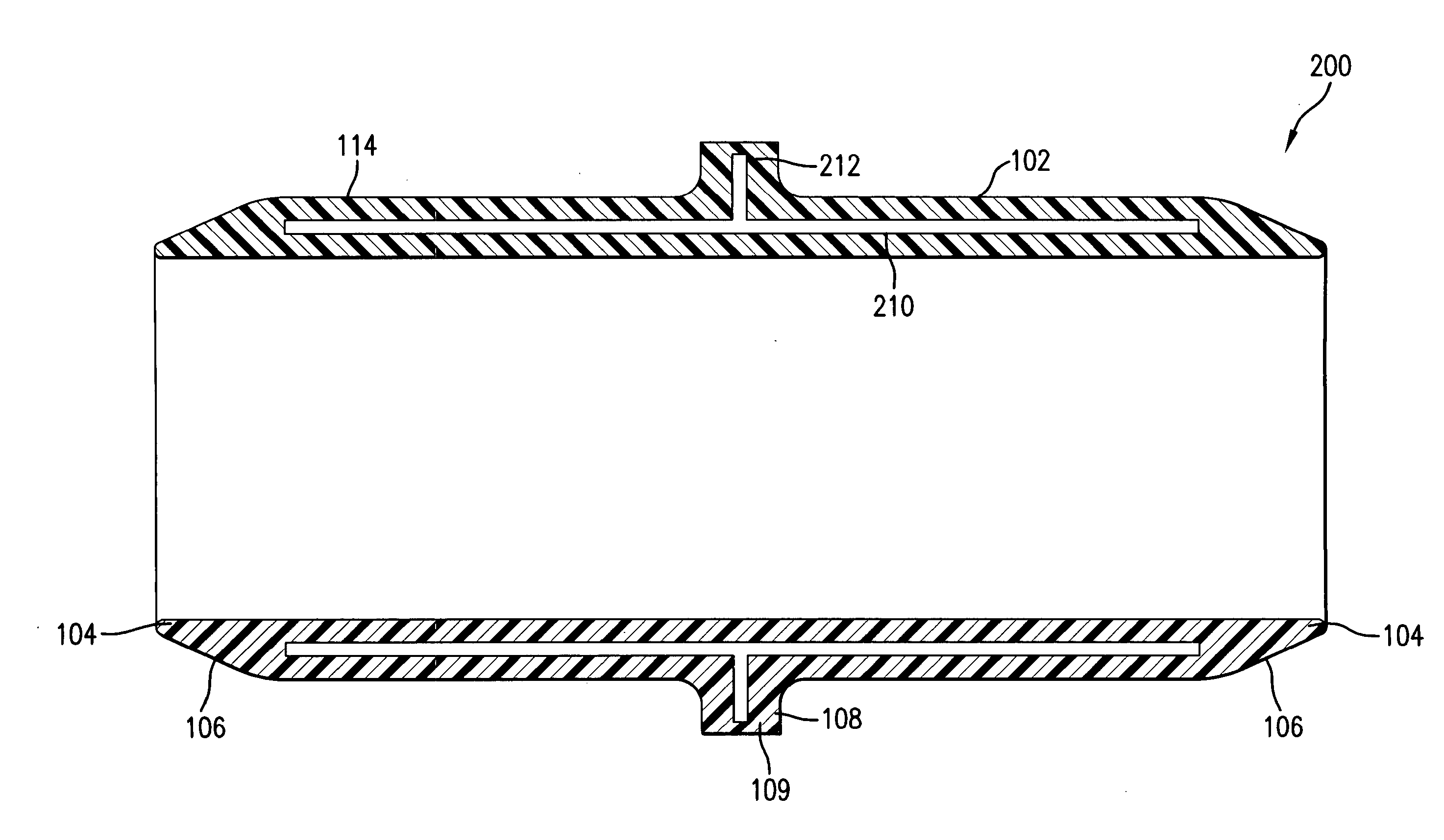
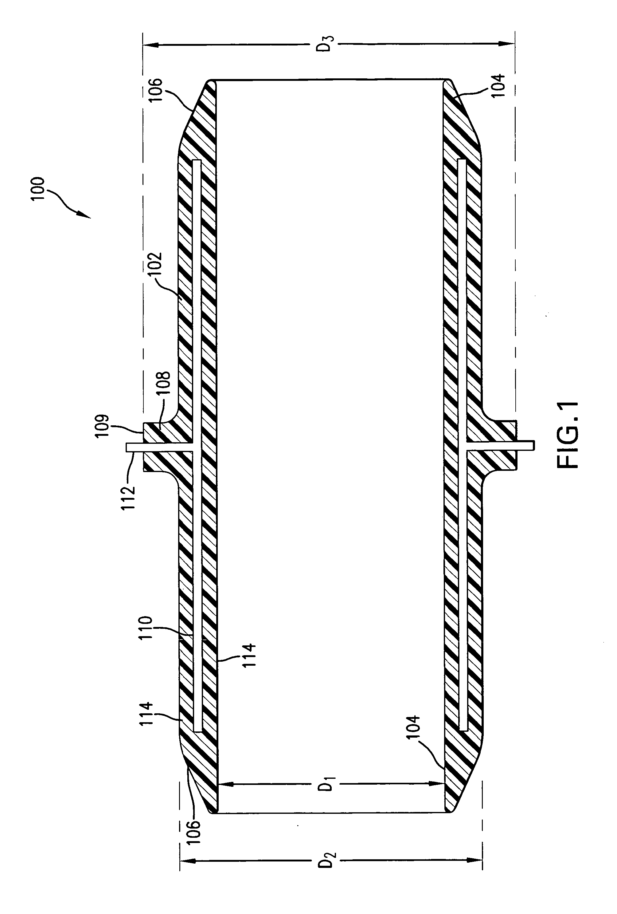
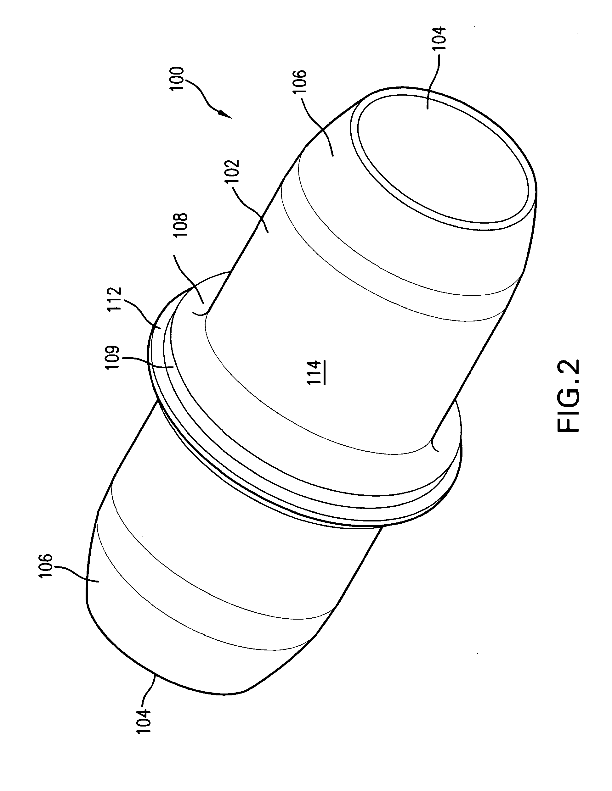
[0047]FIGS. 4-6 show another exemplary embodiment of a coupling 200 constructed in accordance with the present disclosure. The coupling 200 of FIGS. 4-6 is similar to the coupling 100 of FIGS. 1-3 such that similar elements are labeled with the same reference characters. In the embodiment 200 of FIGS. 4-6, however, a core 210 of the coupling 200 is provided with a radially extending portion 212 that extends into the flange 108 but does not extend out of the radial outer surface 109 of the flange 108.

[0048]The core 210 in this embodiment 200 is comprised of material that is magnetically permeable, i.e., ferromagnetic, so that the core can be heated by induction heating. Without being limited to any particular theory, induction heating uses an externally positioned electrical coil. To create heat by induction heating, current is circulated around an internally positioned ferromagnetic material, usually with the current being circulated at a very high frequency. The circulating current...

embodiment 300

[0050]Examples of ferromagnetic materials for the core 210 include carbon steel, iron, carbon, and carbon-reinforced thermoplastic materials. The carbon reinforced thermoplastic version might comprise a central tube material that is manufactured by winding and consolidating unidirectionally extruded thermoplastic tape (e.g., polypropylene, polyethylene, PVDF, etc.) that is reinforced with unidirectional carbon fibers extruded into the tape. Such construction would make the core 210 not only susceptible to being heated by induction heating from an external source, but it would also be exceptionally strong, i.e. stronger than even that of a solid metallic material, yet lightweight. The core 210 may or may not have a radially extending portion, as is illustrated in the embodiment 300 of FIGS. 7-8. In the exemplary embodiment of FIGS. 7-8, the coupling 300 also does not have a flange. Alternatively, the coupling 300 could have a flange extending from the body 102, but no radially extend...


PUM

PropertyMeasurementUnit
angleaaaaaaaaaa
angleaaaaaaaaaa
angleaaaaaaaaaa

Abstract

A coupling for joining socket ends of multilayer tubing through electrofusion including a central body having opposing male ends. A core at least partially surrounds the central body and an outer layer encloses the core and central body. The outer layer defines a flange protruding radially outwardly from the central body, wherein the core includes a portion that extends radially outwardly through the flange and out of the flange so that the core can be directly heated by an external heating element.

Description

TECHNICAL FIELD OF THE DISCLOSURE[0001]The present disclosure relates to a joint and a joining method for multilayer composite tubing having at least one middle layer of malleable metal. The joint and joining method prevent the middle metal layer from being exposed to liquid flow within coupled tubes so that the tubes can meet stringent sanitary requirements.BACKGROUND OF THE DISCLOSURE[0002]Potable water piping is one of the highest volume piping products sold worldwide. It is an essential part of virtually all forms of construction, and particularly where there is human occupancy. Traditional materials for conveying potable water in smaller diameters include copper, steel, and plastic pipe and tubing. Within the last fifteen to twenty years cross-linked polyethylene (PEX) tubing has gained popularity because PEX tubing can be delivered in coiled bundles and because PEX tubing can handle most cold and hot water distribution system applications. As the price of copper has risen, use...

Claims


Application Information

Patent Timeline
Patent Type & Authority Applications(United States)
IPC IPC(8): F16L23/00H05B6/10
CPCB29C65/346B29C66/961B29C65/362B29C66/1122B29C66/116B29C66/5221B29C66/52231B29C66/52241B29C66/5229B29C66/52293B29C66/52295B29C66/723B29C66/80B29D23/005B29K2023/06B29K2023/0691B29K2023/12B29K2027/06B29K2027/16B29K2067/006B29K2079/08B29K2083/00B29K2101/12B29K2105/005B29K2105/101B29K2105/24B29K2305/00B29K2305/02B29K2305/10B29K2305/12B29K2307/00B29K2309/08B29K2995/0008B29L2009/003B29L2031/243B29L2031/246F16L47/03B29C65/3468B29C66/91214B29C66/91641B29C66/91431B29C65/3492B29C65/3644B29C65/3476B29C66/5223B29C65/3696B29C65/3676B29C65/3684B29C66/91231B29C66/91421B29C65/00B29C65/72B29C66/1222B29C66/1224B29C66/1282B29C66/1286B29C66/12881B29C66/636B29C66/71B29C66/7212B29C66/72141B29C66/72321B29C66/73756B29C66/7392B29C66/73921B29C66/73941B29C66/976B29K2307/04B29K2023/04B29K2023/10
Inventor ZIU, CHRISTOPHER G.
Owner ORION ENTERPRISES
Learn More