
Semiconductor Device Package Structure and Method for the Same

a technology of semiconductor devices and package structures, applied in semiconductor devices, semiconductor/solid-state device details, electrical apparatus, etc., can solve the problems of time-consuming manufacturing process, inability to meet the demand of producing smaller chips with high-density elements on the chip, and inability to meet the demand of producing smaller chips. , to achieve the effect of improving mechanical reliability, shrinking size, and excellent cte matching performan

Inactive Publication Date: 2010-12-02
KING DRAGON INT
View PDF4 Cites 141 Cited by
  • Summary
  • Abstract
  • Description
  • Claims
  • Application Information

AI Technical Summary

Benefits of technology

[0010]The object of the present invention is to provide a fan-out panel level packaging with excellent CTE matching performance and shrinkage size.
[0011]The further object of the present invention is to provide a fan-out panel level packaging with a substrate having die opening window to improve the mechanical reliability and shrinking the device size.
[0012]The further object of the present invention is to provide a method of panel substrate which has embedded dice inside with simple way to redistribute the die / chip and substrate and fill into the adhesion materials as stress buffer layer to adhesive the several materials together to form the structure of panel substrate.
[0013]The further object of the present invention is to provide a fan-out panel level packaging having dual build-up layers for increasing the number of fan-out traces and provide the system in package solution. Therefore, the package of the present invention can improve the ability of heat dissipation through double build-up layer to redistribute the pitch of pads and dimension of conductive trace.

Problems solved by technology

As a semiconductor become more complicated, the traditional package technique, for example lead frame package, flex package, rigid package technique, can't meet the demand of producing smaller chip with high density elements on the chip.
Therefore, these techniques are time consuming for manufacturing process.
Since the chip package technique is highly influenced by the development of integrated circuits, therefore, as the size of electronics has become demanding, so does the package technique.
Though the advantages of WLP technique mentioned above, some issues still exist influencing the acceptance of WLP technique.
For instance, the CTE difference (mismatching) between the materials of a structure of WLP and the mother board (PCB) becomes another critical factor to mechanical instability of the structure, the total terminal array number be limited by chip size area and no way to do the multi-chip and system in package by using entire silicon wafer before dicing the wafer.
Furthermore, it creates a poor reliability and yield due to the dielectric layer too thick (dielectric layers 22 and 16), and the CTE (Coefficient of Thermal Expansion) mismatching between dielectric layers 22, 16 and metal 30 and material 20, etc.
Further, the prior art suffers complicated processes to form the “Panel substrate” type package.
It is unlikely to control the surface of die and compound at same level due to warp after heat curing the compound or epoxy, the CMP process may be needed to polish the uneven surface.
The cost is therefore increased.

Method used


Image

  • Semiconductor Device Package Structure and Method for the Same
  • Semiconductor Device Package Structure and Method for the Same
  • Semiconductor Device Package Structure and Method for the Same

Examples


Embodiment Construction

[0040]The invention will now be described in greater detail with preferred embodiments of the invention and illustrations attached. Nevertheless, it should be recognized that the preferred embodiments of the invention is only for illustrating. Besides the preferred embodiment mentioned here, present invention can be practiced in a wide range of other embodiments besides those explicitly described, and the scope of the present invention is expressly not limited expect as specified in the accompanying Claims.

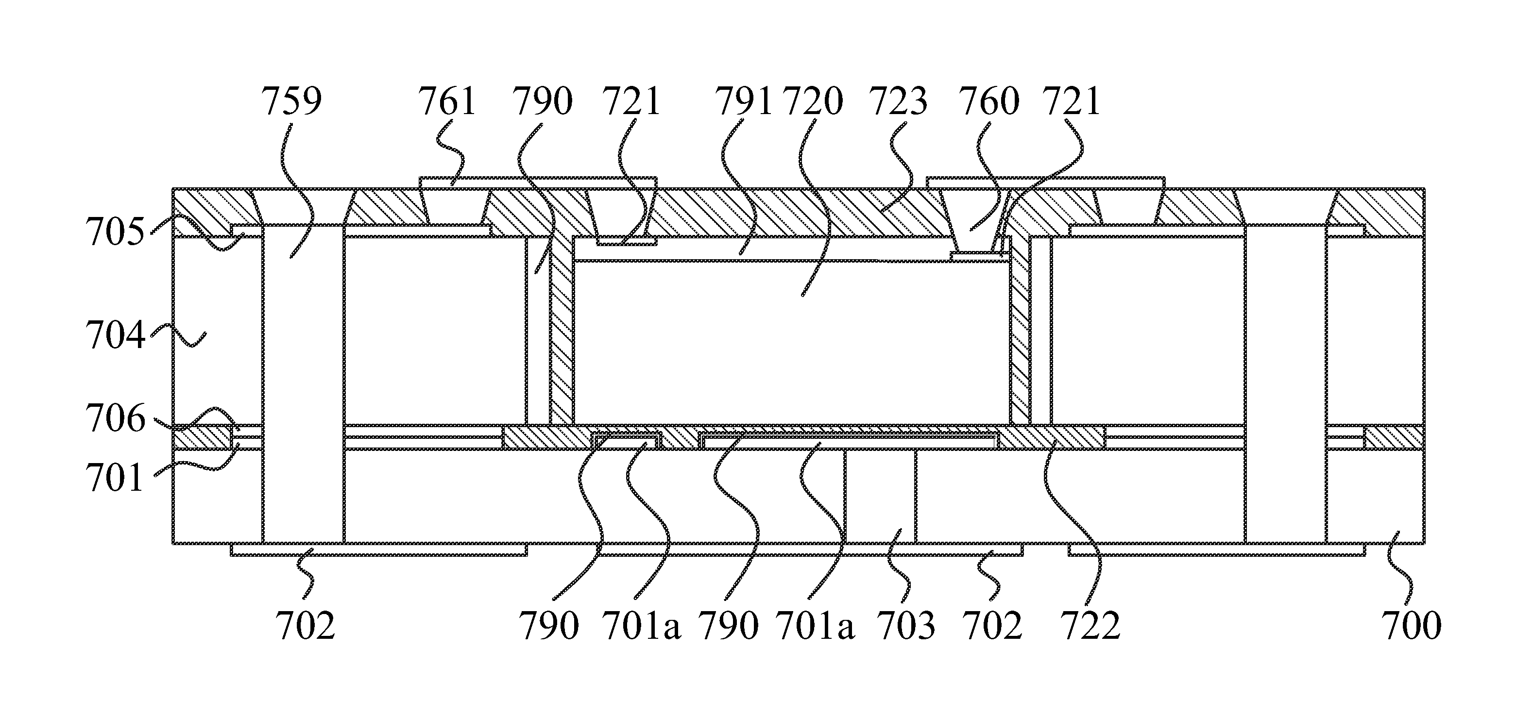
[0041]The present invention discloses a substrate structure with die (or multi-chips) embedded and dual build-up layers formed over the both side-surfaces, shown in FIG. 12, and it illustrates a cross sectional view of system in package (SIP) structure which includes a substrate having die embedded inside with double side build up layers and passive components, WL-CSP, CSP, BGA, Flip Chip etc. surface mounting on top build up layers and terminal pins on opposite side according to ...


PUM


Abstract

The present invention discloses a semiconductor device package and the method for the same. The method includes preparing a first substrate and a second substrate; opening a die opening window through the second substrate by using laser or punching; preparing an adhesion material; attaching the first substrate to the second substrate by the adhesion material; aligning a die by using the aligning mark of the die metal pad and attaching the die onto the die metal pad with force by the adhesion material; forming a first dielectric layer on top surfaces of the second substrate and the die and pushing the first dielectric layer into gap between the side wall of the die and the side wall of the die opening window under vacuum condition; opening a plurality of via openings in the first dielectric layer; and forming a redistribution layer in the plurality of via openings and on the first dielectric layer.

Description

CROSS-REFERENCE[0001]The present application is a continuation-in-part (CIP) application of a pending U.S. application Ser. No. 12 / 232,847, entitled “Substrate Structure with Die Embedded Inside and Dual Build-up Layers over Both Side Surfaces and Method of the Same”, and filed on Sep. 25, 2008, which is incorporated herein by reference in its entirety.TECHNICAL FIELD[0002]This invention relates to a substrate structure with embedded dice inside to form panel level packaging, and more particularly to a fan-out panel level package with dual build up layers formed over the both side-surfaces to improve the reliability and to reduce the device size, especially in thickness.DESCRIPTION OF RELATED ART[0003]In the field of semiconductor devices, the device density is increased and the device dimension is reduced, continuously. The demand for the packaging or interconnecting techniques in such high density devices is also increased to fit the situation mentioned above. Conventionally, in t...

Claims


Application Information

Patent Timeline
Patent Type & Authority Applications(United States)
IPC IPC(8): H01L23/52H01L21/50
CPCH01L21/6835H01L23/49816H01L23/5384H01L23/5389H01L23/544H01L24/16H01L24/24H01L24/31H01L24/82H01L24/83H01L24/97H01L25/105H01L25/16H01L2221/68354H01L2221/68359H01L2223/54426H01L2223/54473H01L2223/5448H01L2224/24225H01L2224/24227H01L2224/73267H01L2224/82039H01L2224/82047H01L2224/83101H01L2224/83121H01L2224/8385H01L2224/92244H01L2224/97H01L2924/01013H01L2924/01015H01L2924/01029H01L2924/01047H01L2924/01075H01L2924/01078H01L2924/01079H01L2924/01082H01L2924/07802H01L2924/09701H01L2924/14H01L2924/15153H01L2924/1517H01L2924/15192H01L2924/15311H01L2924/19041H01L2924/19043H01L2924/0132H01L2924/0133H01L2924/0134H01L24/29H01L2224/2919H01L2924/01006H01L2924/01033H01L2924/014H01L2924/0665H01L2224/16225H01L2224/32225H01L2924/10253H01L2224/16235H01L2224/82H01L2224/83H01L2924/00H01L2924/01022H01L2924/01028H01L2924/3512H01L2924/351H01L2224/0557H01L2224/05573H01L2224/05624H01L2924/181H01L2224/05571H01L2924/00014H01L2224/0554H01L2924/00012H01L2224/05599H01L2224/0555H01L2224/0556
Inventor YANG, WEN-KUN
Owner KING DRAGON INT
Learn More