Microneedle Devices and Methods of Manufacture and Use Thereof

a technology of microneedle and manufacturing method, which is applied in the field of microneedle devices and methods of manufacture, can solve the problems of patient compliance, drug cannot be effectively delivered in this manner, and drugs cannot effectively diffuse across the intestinal mucosa, etc., and achieves the effect of facilitating transport, pain, or irritation of tissue, and minimal or no damag

Inactive Publication Date: 2010-12-09
GEORGIA TECH RES CORP
View PDF104 Cites 23 Cited by
  • Summary
  • Abstract
  • Description
  • Claims
  • Application Information

AI Technical Summary

Benefits of technology

[0016]Microneedle devices for transport of molecules, including drugs and biological molecules, across tissue, and methods for manufacturing the devices, are provided. The microneedle devices permit drug delivery or removal of body fluids at clinically relevant rates across skin or other tissue barriers, with minimal or no damage, pain, or irritation to the tissue. Microneedles can be formed of biodegradable or non-biodegradable polymeric materials or metals. In a preferred embodiment, the microneedles are formed of a biodegradable polymer. In another preferred embodiment, the device includes a means for temporarily securing the microneedle device to the biological barrier to facilitate transport.

Problems solved by technology

However, a frequent limitation of these drugs is their delivery: how to transport drugs across biological barriers in the body (e.g., the skin, the oral mucosa, the blood-brain barrier), which normally do not transport drugs at rates that are therapeutically useful or optimal.
However, many drugs cannot be effectively delivered in this manner, due to degradation in the gastrointestinal tract and / or elimination by the liver.
Moreover, some drugs cannot effectively diffuse across the intestinal mucosa.
Patient compliance may also be a problem, for example, in therapies requiring that pills be taken at particular intervals over a prolonged time.
While effective for this purpose, needles generally cause pain; local damage to the skin at the site of insertion; bleeding, which increases the risk of disease transmission; and a wound sufficiently large to be a site of infection.
The needle technique also is undesirable for long term, controlled continuous drug delivery.
Similarly, current methods of sampling biological fluids are invasive and suffer from the same disadvantages.
No alternative methodologies are currently in use.
Proposed alternatives to the needle require the use of lasers or heat to create a hole in the skin, which is inconvenient, expensive, or undesirable for repeated
However, this method is not useful for many drugs, due to the poor permeability (i.e. effective barrier properties) of the skin.
Few drugs have the necessary physiochemical properties to be effectively delivered through the skin by passive diffusion.
While providing varying degrees of enhancement, these techniques are not suitable for all types of drugs, failing to provide the desired level of delivery.
In some cases, they are also painful and inconvenient or impractical for continuous controlled drug delivery over a period of hours or days.

Method used


Image

  • Microneedle Devices and Methods of Manufacture and Use Thereof
  • Microneedle Devices and Methods of Manufacture and Use Thereof
  • Microneedle Devices and Methods of Manufacture and Use Thereof

Examples


example 1

Fabrication of Solid Silicon Microneedles

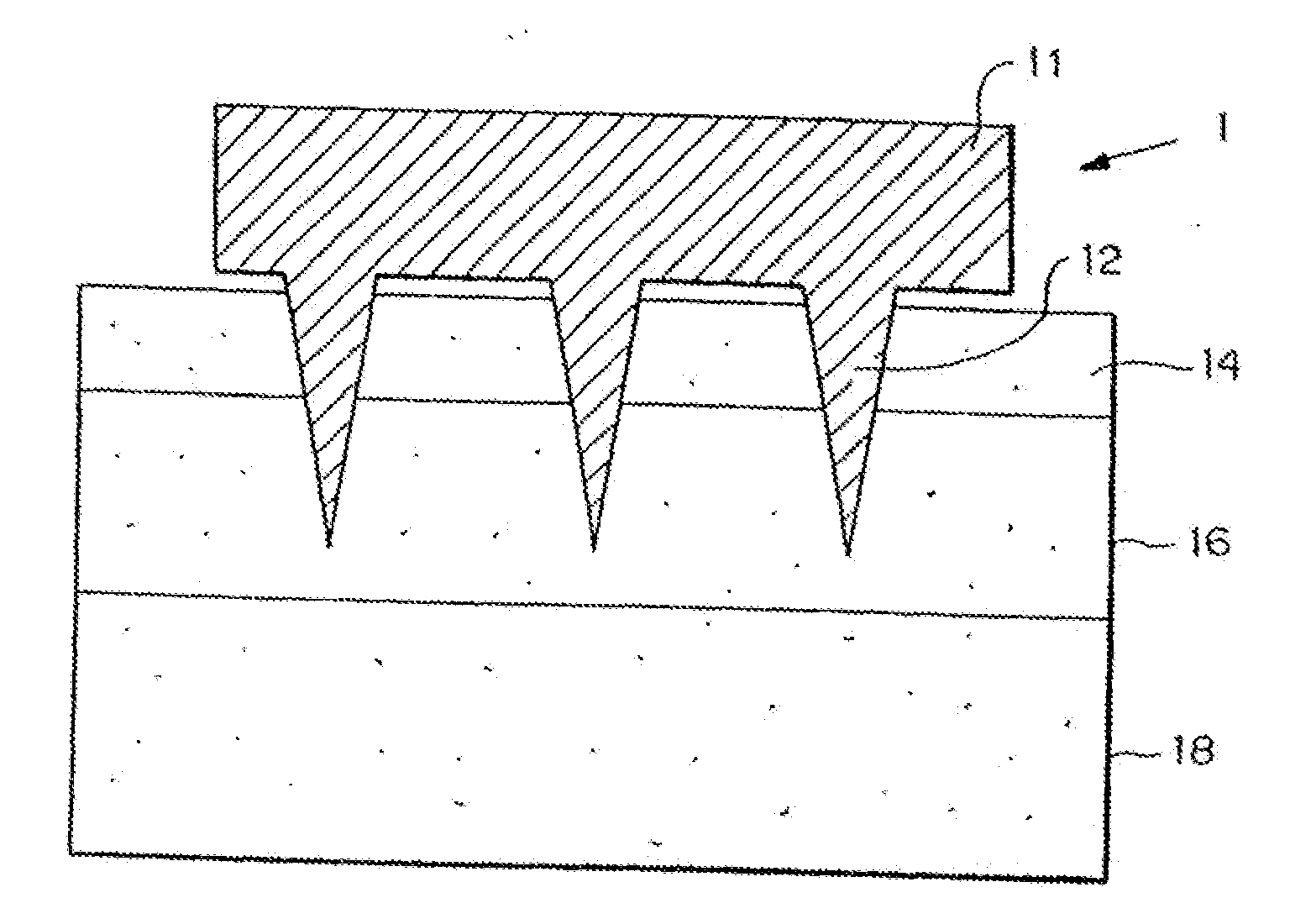
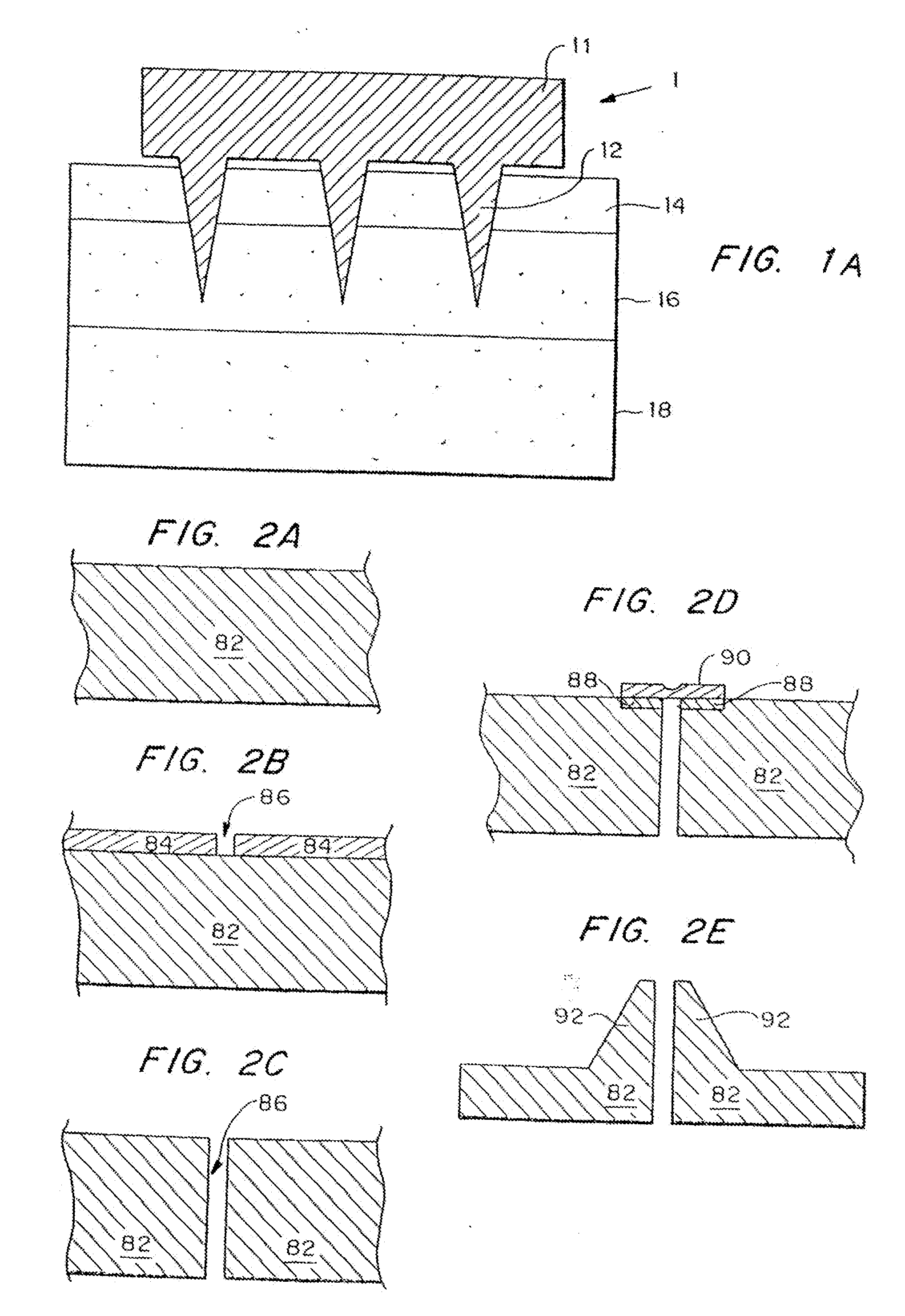
[0138]A chromium masking material was deposited onto silicon wafers and patterned into dots having a diameter approximately equal to the base of the desired microneedles. The wafers were then loaded into a reactive ion etcher and subjected to a carefully controlled plasma based on fluorine / oxygen chemistries to etch very deep, high aspect ratio valleys into the silicon. Those regions protected by the metal mask remain and form the microneedles.

[0139]-oriented, prime grade, 450-550 μm thick, 10-15 Ω-cm silicon wafers (Nova Electronic Materials Inc., Richardson, Tex.) were used as the starting material. The wafers were cleaned in a solution of 5 parts by volume deionized water, 1 part 30% hydrogen peroxide, and 1 part 30% ammonium hydroxide (J. T. Baker, Phillipsburg, N.J.) at approximately 80° C. for 15 minutes, and then dried in an oven (Blue M Electric, Watertown, Wis.) at 150° C. for 10 minutes. Approximately 1000 Å of chromium (Mat-Vac Tec...

example 2

Transdermal Transport Using Solid Microneedles

[0142]To determine if microfabricated microneedles could be used to enhance transdermal drug delivery, arrays of microneedles were made using a deep plasma etching technique. Their ability to penetrate human skin without breaking was tested and the resulting changes in transdermal transport were measured.

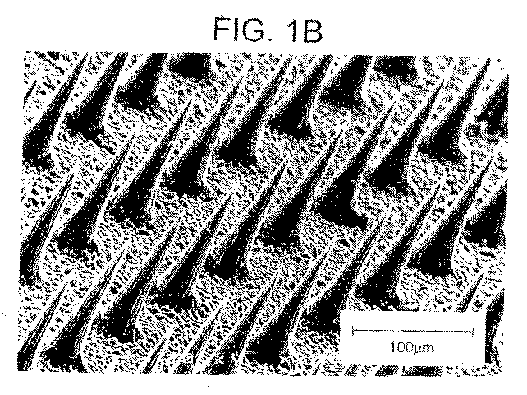
[0143]Arrays of microneedles were fabricated having extremely sharp tips (radius of curvature less than 1 μm) which facilitate easy piercing into the skin, and are approximately 150 μm long. Because the skin surface is not flat due to dermatoglyphics and hair, the full length of these microneedles will not penetrate the skin. All experiments were, performed at room temperature (23±2° C.).

[0144]The ability of the microneedles to pierce skin without breaking was then tested. Insertion of the arrays into skin required only gentle pushing. Inspection by light and electron microscopy showed that more than 95% of microneedles within an array p...

example 3

Fabrication of Silicon Microtubes

[0148]Three-dimensional arrays of microtubes were fabricated from silicon, using deep reactive ion etching combined with a modified black silicon process in a conventional reactive ion etcher. The fabrication process is illustrated in FIGS. 5a-d. First, arrays of 40 μm diameter circular holes 32 were patterned through photoresist 34 into a 1 μm thick SiO2 layer 36 on a two inch silicon wafer 38 (FIG. 5a). The wafer 38 was then etched using deep reactive ion etching (DRIE) (Laermer, et al., “Bosch Deep Silicon Etching: Improving Uniformity and Etch Rate for Advanced MEMS Applications,”Micro Electro Mechanical Systems, Orlando, Fla., USA (Jan. 17-21, 1999)) in an inductively coupled plasma (ICP) reactor to etch deep vertical holes 40. The deep silicon etch was stopped after the holes 40 are approximately 200 μm deep into the silicon substrate 38 (FIG. 5b) and the photoresist 34 was removed. A second photolithography step patterned the remaining SiO2 la...


PUM

PropertyMeasurementUnit
diameteraaaaaaaaaa
outer diameteraaaaaaaaaa

Abstract

Microneedle devices are provided for transport of therapeutic and biological molecules across tissue barriers and for use as microflameholders. In a preferred embodiment for transport across tissue, the microneedles are formed of a biodegradable polymer. Methods of making these devices, which can include hollow and / or porous microneedles, are also provided. A preferred method for making a microneedle includes forming a micromold having sidewalls which define the outer surface of the microneedle, electroplating the sidewalls to form the hollow microneedle, and then removing the micromold from the microneedle. In a preferred method of use, the microneedle device is used to deliver fluid material into or across a biological barrier from one or more chambers in fluid connection with at least one of the microneedles. The device preferably further includes a means for controlling the flow of material through the microneedles. Representative examples of these means include the use of permeable membranes, fracturable impermeable membranes, valves, and pumps.

Description

CROSS-REFERENCE TO RELATED APPLICATIONS[0001]This is a continuation-in-part of U.S. Ser. No. 09 / 095,221, filed Jun. 10, 1998.STATEMENT REGARDING FEDERALLY SPONSORED RESEARCH[0002]The government has certain rights in this invention by virtue of Grant Number BES-9813321 awarded by the U.S. National Science Foundation to Mark R. Prausnitz, and support from the Defense Advanced Research Projects Agency (DARPA) to Mark G. Allen.BACKGROUND OF THE INVENTION[0003]This invention is generally in the field of devices for the transport of therapeutic or biological molecules across tissue barriers, such as for drug delivery.[0004]Numerous drugs and therapeutic agents have been developed in the battle against disease and illness. However, a frequent limitation of these drugs is their delivery: how to transport drugs across biological barriers in the body (e.g., the skin, the oral mucosa, the blood-brain barrier), which normally do not transport drugs at rates that are therapeutically useful or op...

Claims


Application Information

Patent Timeline
Patent Type & Authority Applications(United States)
IPC IPC(8): A61M5/00A61B5/00A61B5/15A61B17/20A61K9/70A61M37/00A61N1/30B81C1/00
CPCA61B5/14514A61B5/14532A61B17/205A61K9/0021A61M37/0015A61M2037/003A61M2037/0053A61N1/303B81B2201/055B81C1/00111A61B5/150282A61B5/150984A61B5/150022A61B2010/008B33Y80/00
Inventor ALLEN, MARK G.PRAUSNITZ, MARK R.MCALLISTER, DEVIN V.CROS, FLORENT PAUL MARCEL
Owner GEORGIA TECH RES CORP
Why Eureka
Try Eureka